Concrete Quantity Estimation Guide (2026): Formula, Calculations, Cost & Material Estimation

Concrete Quantity Estimation Guide (2026): Formula, Calculations, Cost & Material Estimation

Accurate concrete quantity estimation is one of the most important steps in any construction project. Whether you’re pouring a residential patio, driveway, foundation, commercial floor, or structural element, estimating the correct amount of concrete helps control costs, reduce material waste, and keep the project on schedule. Ordering too little concrete can interrupt the pour, create cold joints, and delay construction, while ordering too much increases unnecessary expenses and material waste. A proper estimate ensures you purchase only what the project requires.

In the United States, ready-mix concrete is the most common choice for medium and large construction projects because it provides consistent quality, faster placement, and better efficiency than mixing concrete on-site. For small repairs, fence posts, sidewalks, or DIY projects, bagged concrete mixes (such as 40 lb, 60 lb, or 80 lb bags) remain a practical and cost-effective option. Choosing between ready-mix and bagged concrete depends on the project’s size, required strength, and overall budget.

This Concrete Quantity Estimation Guide explains everything you need to accurately calculate concrete requirements for the most common structural elements, including slabs, footings, beams, columns, walls, staircases, and circular concrete sections. You’ll learn the formulas, measurement methods, unit conversions, practical examples, and estimation tips used throughout the USA, helping you order the right amount of concrete with confidence while minimizing waste and avoiding costly mistakes.

Basic Concepts of Concrete

Before estimating concrete quantities, it’s important to understand the basic properties of concrete, the common mix strengths used in the United States, and the standard measurement units used in construction. These fundamentals help ensure accurate material calculations and proper concrete selection for different types of projects.

Common Concrete Mix Types (USA)

Concrete is available in different compressive strengths, measured in PSI (Pounds per Square Inch). The required strength depends on the structural load and intended application.

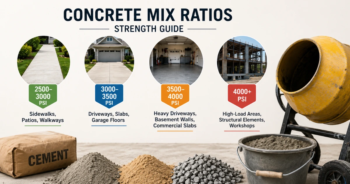
Concrete StrengthCommon ApplicationsTypical Use
2,500 PSISidewalks, patios, walkwaysLight residential projects
3,000 PSIDriveways, garage floors, slabsMost common residential concrete
3,500 PSIFoundations, footings, reinforced slabsResidential and light commercial
4,000 PSIBasement walls, structural slabs, exterior concreteHigh-strength residential construction
5,000+ PSICommercial buildings, bridges, heavy-duty pavementsIndustrial and structural applications

Note: In most U.S. residential construction, 3,000 PSI and 4,000 PSI concrete are the most commonly specified mixes because they provide an excellent balance of strength, durability, and cost.

Key Components of Concrete

Concrete is made by combining four primary ingredients, each serving a specific purpose.

1. Cement

Cement is the binding material that chemically reacts with water (hydration) to hold all the ingredients together. Ordinary Portland Cement (OPC) is the most commonly used cement in residential construction.

2. Aggregates

Aggregates make up approximately 60–75% of the concrete volume and provide strength and stability.

  • Fine Aggregate: Sand
  • Coarse Aggregate: Gravel or crushed stone

The size and quality of aggregates significantly affect concrete strength and durability.

3. Water

Water activates the cement and makes the concrete workable. Maintaining the correct water-to-cement (w/c) ratio is essential because excessive water reduces strength and increases cracking.

4. Admixtures

Admixtures are specialized chemicals added to improve concrete performance. Common examples include:

  • Water reducers for better workability
  • Accelerators for faster setting in cold weather
  • Retarders for hot-weather placements
  • Air-entraining agents for improved freeze-thaw resistance
  • Superplasticizers for high-flow concrete without adding extra water

Standard Measurement Units in the USA

Concrete quantity estimation in the United States follows Imperial units, making accurate unit conversions essential before placing an order.

  • Concrete is ordered in Cubic Yards (yd³).
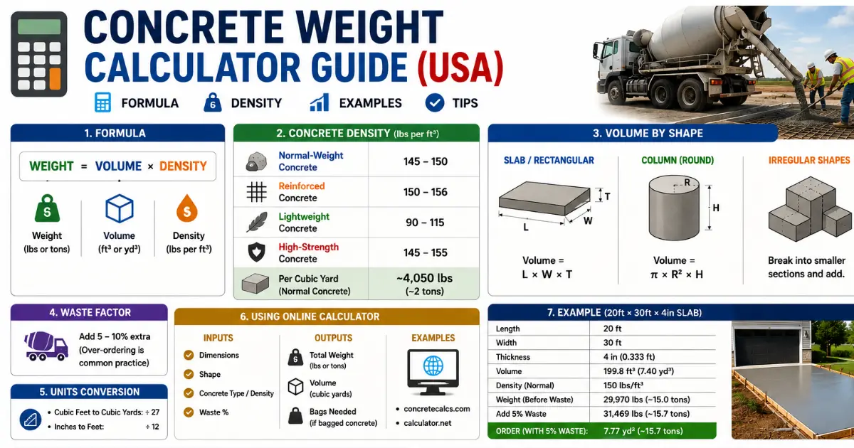
  • 1 Cubic Yard = 27 Cubic Feet (ft³).
  • Project dimensions are typically measured in feet and inches.
  • Thickness is usually specified in inches, then converted to feet for volume calculations.

Common Unit Conversions

MeasurementEquivalent
1 Cubic Yard27 Cubic Feet
1 Foot12 Inches
6 Inches0.5 Feet
4 Inches0.333 Feet
8 Inches0.667 Feet
12 Inches1 Foot

Why These Basics Matter

Understanding concrete mix strengths, material components, and U.S. measurement units makes quantity estimation far more accurate. Whether you’re calculating concrete for slabs, footings, beams, columns, walls, or foundations, knowing the correct mix type and converting dimensions properly helps prevent ordering errors, reduces material waste, and ensures your project stays on budget and on schedule.

Fundamental Calculation Formula

Accurate concrete estimation starts with one simple volume formula. Whether you’re calculating concrete for a slab, footing, beam, column, wall, or foundation, the same principle applies—find the volume first, then convert it into cubic yards, which is the standard unit used for ordering ready-mix concrete in the United States.

Step 1: Calculate Concrete Volume

Use the following basic formula to calculate the volume in cubic feet:

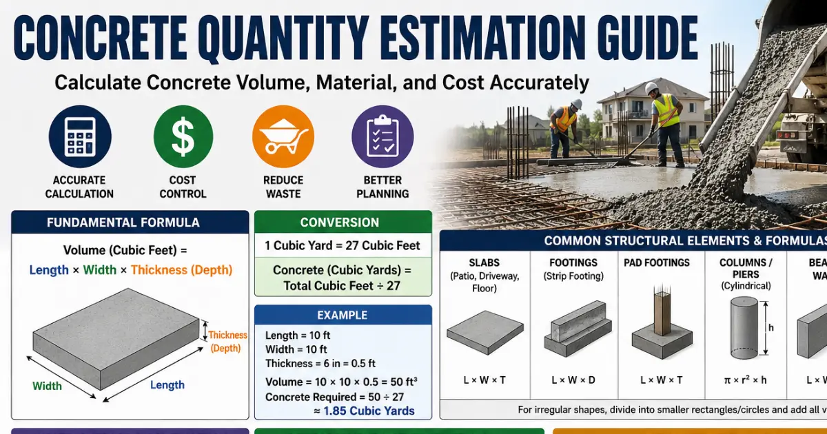
Volume (Cubic Feet) = Length × Width × Thickness (Depth)

Where:

  • Length = Measured in feet
  • Width = Measured in feet
  • Thickness (Depth) = Measured in feet

If the thickness is given in inches, convert it to feet before performing the calculation.

Step 2: Convert Cubic Feet to Cubic Yards

Since ready-mix concrete is sold in cubic yards, convert the calculated volume using this formula:

Concrete (Cubic Yards) = Total Cubic Feet ÷ 27

Remember:
1 Cubic Yard = 27 Cubic Feet

Step 3: Convert Thickness from Inches to Feet

Concrete thickness is usually specified in inches, while volume calculations require feet.

Use this simple conversion:

Thickness (Feet) = Thickness (Inches) ÷ 12

Common Thickness Conversions

Thickness (Inches)Thickness (Feet)
4 in0.333 ft
5 in0.417 ft
6 in0.500 ft
8 in0.667 ft
10 in0.833 ft
12 in1.000 ft

Worked Example

Suppose you’re pouring a concrete slab with the following dimensions:

  • Length: 10 ft
  • Width: 10 ft
  • Thickness: 6 inches

Step 1: Convert Thickness

6 inches ÷ 12 = 0.5 ft

Step 2: Calculate Volume in Cubic Feet

Volume = 10 × 10 × 0.5 = 50 Cubic Feet

Step 3: Convert to Cubic Yards

50 ÷ 27 = 1.85 Cubic Yards

Final Result

ItemValue
Length10 ft
Width10 ft
Thickness6 in (0.5 ft)
Volume50 Cubic Feet
Concrete Required1.85 Cubic Yards

Different Structural Elements for Concrete Quantity Estimation

Different structural components require slightly different calculation methods because their shapes and dimensions vary. While the basic principle remains calculating volume, using the correct formula for each structural element ensures an accurate concrete estimate and minimizes material waste.

1. Concrete Slabs (Patios, Driveways & Floors)

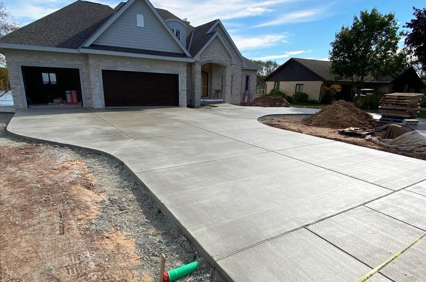
Concrete slabs are the most common residential concrete structures in the United States. They are typically rectangular, making volume calculations straightforward.

Formula

Volume = Length × Width × Thickness

Where:

  • Length = Feet
  • Width = Feet
  • Thickness = Feet (convert inches to feet)

Common Residential Slab Thickness

ApplicationTypical Thickness
Sidewalks4 inches
Patios4 inches
Garage Floors4–5 inches
Residential Driveways5–6 inches
Heavy Vehicle Areas6 inches or more

Example

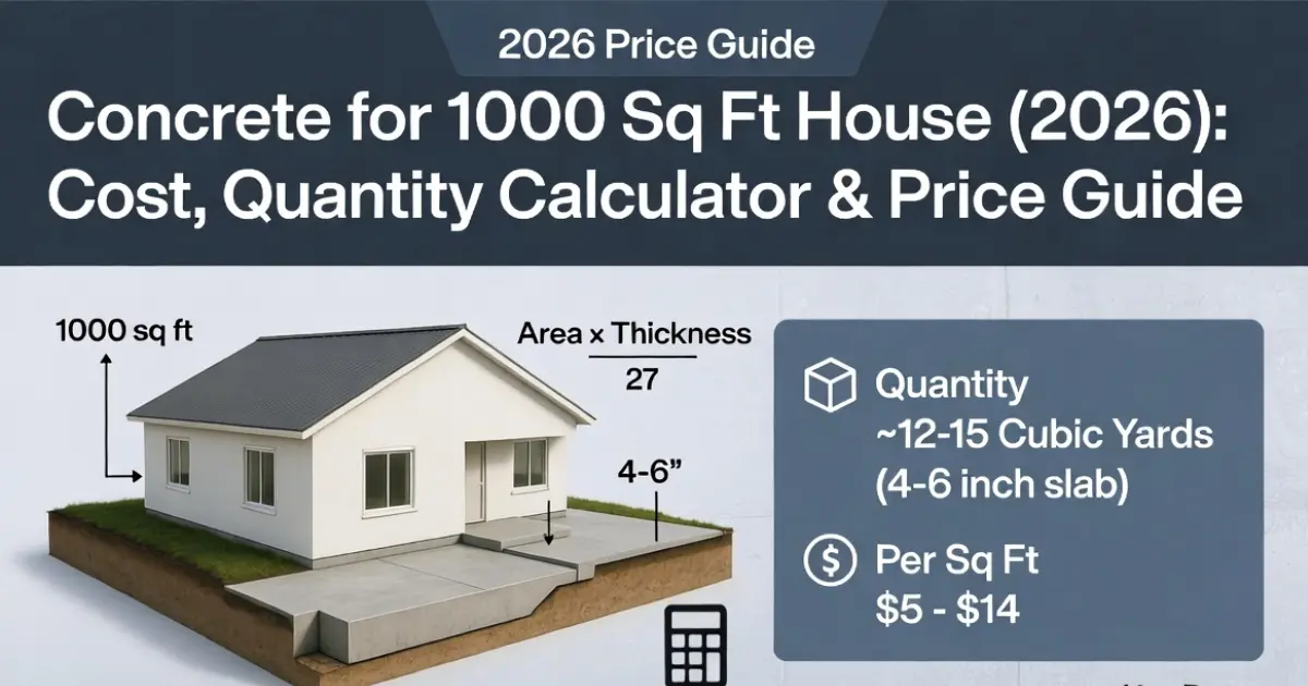
A driveway measuring 20 ft × 12 ft × 5 inches:

  • Thickness = 5 ÷ 12 = 0.417 ft
  • Volume = 20 × 12 × 0.417 = 100.08 cubic feet
  • Concrete Required = 100.08 ÷ 27 = 3.71 cubic yards

2. Footings & Foundations

Footings transfer structural loads safely into the soil. Their shape may be simple or more complex depending on the design.

Strip Footings

Used beneath continuous foundation walls.

Formula

Volume = Length × Width × Depth

Pad Footings

Used beneath isolated columns.

Formula

Volume = Length × Width × Thickness

T-Shaped or Stepped Footings

Some foundations include wider bases or stepped sections.

For these designs:

  • Divide the footing into simple rectangular sections.
  • Calculate each section separately.
  • Add all section volumes together.

If exact dimensions vary along the footing, using the average width and average depth provides a practical estimate during planning.

3. Columns & Piers

Concrete columns and drilled piers are generally circular in cross-section.

Formula

Volume = π × r² × Height

Where:

  • π ≈ 3.1416
  • r = Radius (half the diameter)
  • Height = Feet

Example

Column Diameter = 18 inches

Height = 10 feet

Radius = 18 ÷ 2 = 9 inches = 0.75 ft

Volume = 3.1416 × (0.75²) × 10

= 17.67 cubic feet

Concrete Required

17.67 ÷ 27 = 0.65 cubic yards

4. Beams & Walls

Concrete beams and walls are essentially rectangular sections, making them easy to calculate.

Formula

Volume = Length × Width × Depth (or Thickness)

Typical Applications

  • Foundation walls
  • Retaining walls
  • Grade beams
  • Structural beams
  • Shear walls

Example

Wall Dimensions:

  • Length = 30 ft
  • Height = 8 ft
  • Thickness = 8 inches (0.667 ft)

Volume

30 × 8 × 0.667 = 160.08 cubic feet

Concrete Required

160.08 ÷ 27 = 5.93 cubic yards

5. Stairs, Curbs & Gutters

These structural elements contain multiple slopes, steps, or irregular profiles, making direct calculations more difficult.

Recommended Approach

  • Divide the structure into smaller rectangular or triangular sections.
  • Calculate each section individually.
  • Add all calculated volumes together.

For larger commercial projects, using a dedicated online concrete calculator can save time and improve accuracy for complex shapes.

6. Irregular Shapes

Many residential and commercial projects contain curved edges, rounded patios, angled foundations, or custom architectural features.

Best Estimation Method

Break the structure into simple geometric shapes, such as:

  • Rectangles
  • Squares
  • Circles
  • Half circles
  • Triangles

Calculate the concrete volume for each section separately, then add all volumes together to obtain the total concrete requirement.

Example Workflow

  1. Divide the project into manageable sections.
  2. Measure each section individually.
  3. Calculate the volume of every section.
  4. Add all section volumes.
  5. Convert the total cubic feet into cubic yards by dividing by 27.

Quick Reference Table

Structural ElementCalculation FormulaNotes
SlabsLength × Width × ThicknessMost common residential method
Strip FootingsLength × Width × DepthContinuous foundations
Pad FootingsLength × Width × ThicknessIndividual column supports
Columns & Piersπ × r² × HeightCircular concrete members
BeamsLength × Width × DepthRectangular structural members
WallsLength × Height × ThicknessFoundation and retaining walls
StairsDivide into sectionsAdd individual section volumes
Curbs & GuttersSectional calculationsMultiple shapes combined
Irregular ShapesDivide into rectangles/circlesSum all calculated volumes

Waste, Overage and Contingency Factors

Even the most accurate concrete calculations should include a small waste and contingency allowance. Field conditions rarely match design dimensions exactly, and factors such as uneven excavation, spillage, formwork variations, and placement losses can increase the amount of concrete required. Adding an appropriate overage helps prevent shortages, costly delays, and the need for a second concrete delivery.

Standard Waste Allowance

The recommended waste allowance depends on the type and complexity of the project.

Structural ElementRecommended OverageCommon Reasons
Residential Slabs, Patios & Sidewalks5–10%Minor spillage, uneven subgrade, finishing losses
Driveways & Garage Floors5–10%Thickness variations, placement waste
Footings & Foundations10–15%Over-excavation, irregular trenches, soil settlement
Columns & Piers10–15%Formwork leakage, placement losses, overfill
Beams & Walls5–10%Formwork tolerances, consolidation losses
Complex Shapes (Stairs, Curbs, Irregular Sections)10–15%Multiple sections, cutting errors, difficult placement

Tip: Small DIY projects may require a slightly higher percentage because measuring errors have a greater impact on the total volume.

Common Sources of Concrete Waste

Several job-site conditions can increase concrete consumption beyond the calculated quantity.

  • Spillage during transportation or placement.
  • Uneven or poorly compacted subgrade.
  • Over-excavated trenches and footing bases.
  • Formwork leaks or dimensional variations.
  • Pump priming and leftover concrete in equipment.
  • Finishing adjustments and edge corrections.
  • Minor measurement errors during layout.

Accounting for these factors before ordering reduces the risk of running out of concrete during the pour.

Rounding Up Your Order

Ready-mix suppliers typically deliver concrete in cubic yards, so calculated quantities should be rounded up rather than down.

A good practice is to order to the nearest:

  • ¼ cubic yard (0.25 yd³) for smaller residential projects.
  • ½ cubic yard (0.50 yd³) for medium to large pours.

Example

Calculated QuantityRecommended Order
2.18 yd³2.25 yd³
3.42 yd³3.50 yd³
5.78 yd³6.00 yd³
8.12 yd³8.25 yd³

Ordering slightly more concrete is usually far less expensive than stopping work to schedule an additional delivery.

Soil Conditions

Ground conditions can significantly affect the actual amount of concrete needed.

Stable, Well-Compacted Soil

  • Excavations remain close to the design dimensions.
  • Less additional concrete is typically required.

Soft or Loose Soil

  • Excavation sides may collapse.
  • Footings often become wider or deeper than planned.
  • Additional concrete may be needed to fill unexpected voids.

Rocky or Uneven Ground

  • Irregular excavation profiles increase concrete volume.
  • Extra material may be required to achieve a level foundation.

Inspecting and preparing the subgrade before pouring concrete helps improve estimation accuracy and minimizes unnecessary waste.

Weather Considerations (USA)

Weather conditions across the United States can also influence concrete planning and ordering.

Cold Climates

In northern states, winter construction requires additional precautions.

  • Frozen ground should be thawed before placement.
  • Forms and reinforcement should be free of ice and snow.
  • Cold-weather concreting may require accelerators or heated concrete.
  • Extra planning helps avoid delays that can lead to wasted material.

Hot Weather

During summer, concrete can lose workability more quickly.

  • Schedule pours during cooler parts of the day.
  • Use water-reducing or retarding admixtures when appropriate.
  • Ensure adequate labor and equipment are available to place and finish concrete promptly.

Rainy Conditions

Unexpected rainfall can affect excavation quality, subgrade stability, and finishing operations. Monitoring the weather forecast before scheduling a pour helps reduce waste and avoid project interruptions.

Best Practices to Minimize Waste

  • Measure all dimensions carefully before placing an order.
  • Verify excavation depth and width after site preparation.
  • Include the recommended 5–15% waste allowance based on project type.
  • Round the order up to the nearest ¼ or ½ cubic yard.
  • Coordinate delivery timing with the construction crew to minimize placement delays.
  • Use an accurate concrete quantity calculator to verify estimates before ordering.

Key Takeaway

Concrete estimation should always account for waste, overage, and site conditions, not just the calculated volume. For most slabs and flatwork, adding 5–10% is sufficient, while footings, foundations, columns, and other complex structural elements typically require 10–15% to cover over-excavation, uneven bases, and placement losses. Combining a realistic contingency allowance with proper rounding and consideration of soil and weather conditions helps ensure a smooth concrete pour without unnecessary delays or costly reorders.

Reinforcement, Formwork and Other Materials

Estimating concrete volume is only one part of planning a successful construction project. Most structural concrete also requires reinforcement, formwork, and supporting materials to achieve the required strength, durability, and finish. Including these items during the estimation stage helps create a more accurate project budget and prevents delays caused by material shortages.

Reinforcement Estimation

Concrete is strong in compression but relatively weak in tension. Reinforcement materials such as rebar and wire mesh improve tensile strength, control cracking, and increase the overall structural performance of concrete.

Rebar (Reinforcing Steel)

Rebar is commonly used in:

  • Foundations
  • Footings
  • Slabs
  • Beams
  • Columns
  • Retaining walls

The amount of rebar depends on:

  • Structural design requirements
  • Concrete thickness
  • Load conditions
  • Local building codes
  • Bar spacing and bar size

For example, a residential slab may use #3 or #4 reinforcing bars spaced according to the structural drawings, while foundations and columns generally require larger bars with closer spacing.

Important: Rebar should always be estimated using the project’s structural drawings or engineering specifications, as spacing and bar sizes vary from one project to another.

Welded Wire Mesh (WWM)

Wire mesh is commonly installed in residential concrete slabs to help control shrinkage cracks and improve load distribution.

Typical applications include:

  • Sidewalks
  • Patios
  • Garage floors
  • Residential driveways
  • Interior concrete floors

Wire mesh is generally estimated based on the total slab area (square feet) rather than concrete volume.

When calculating the required quantity:

  • Measure the slab area.
  • Include overlaps between adjacent mesh sheets.
  • Allow extra material around edges and openings.

Vapor Barriers

A vapor barrier is a polyethylene sheet installed beneath concrete slabs to reduce moisture migration from the soil into the concrete.

It is commonly recommended for:

  • Basement floors
  • Garage slabs
  • Interior floor slabs
  • Commercial buildings
  • Finished living spaces

Estimation Method

Estimate the vapor barrier based on the slab’s surface area.

Include additional material for:

  • Sheet overlaps
  • Edge turn-ups
  • Waste during installation

A practical allowance of 5–10% extra material is often included to account for overlaps and trimming.

Formwork Material Estimation

Formwork provides temporary support that holds fresh concrete in place until it gains sufficient strength. Proper formwork is essential for maintaining the correct dimensions, alignment, and surface finish.

Materials Commonly Used

  • Plywood sheets
  • Dimensional lumber
  • Steel forms
  • Aluminum forms
  • Form ties and braces
  • Stakes and supports

How to Estimate Formwork

Unlike concrete, formwork is estimated by the surface area that requires support rather than by volume.

The required formwork depends on:

  • Height of the concrete member
  • Perimeter or length of the structure
  • Number of exposed sides
  • Shape and complexity of the project

For example:

  • Slabs usually require edge forms only.
  • Footings require forms only where soil cannot act as a natural form.
  • Beams and columns require forms on multiple sides.
  • Walls require full-height formwork on both faces.

For projects with repeated shapes, reusable form systems can significantly reduce material costs.

Other Supporting Materials

In addition to concrete and reinforcement, many projects require several auxiliary materials.

MaterialPrimary Purpose
Rebar ChairsMaintain proper reinforcement cover
Tie WireSecure reinforcing bars together
Expansion Joint MaterialAllow concrete movement and reduce cracking
Control Joint InsertsHelp control shrinkage cracking
Anchor BoltsConnect structural members to foundations
Curing CompoundRetain moisture for proper concrete curing
Bond BreakersPrevent unwanted bonding between concrete surfaces
Form Release AgentAllow easy removal of formwork without damaging concrete

Material Estimation Checklist

Before ordering materials, verify the following:

  • ✔ Calculate the total concrete volume in cubic yards.
  • ✔ Estimate rebar according to the structural drawings and specified spacing.
  • ✔ Measure slab area for welded wire mesh requirements.
  • ✔ Calculate vapor barrier coverage, including overlaps and waste.
  • ✔ Estimate formwork based on the exposed surface area and project geometry.
  • ✔ Include supporting materials such as chairs, tie wire, expansion joints, and curing products.

Tools & Resources for Accurate Estimation

Using the right tools can make concrete quantity estimation faster, more accurate, and less prone to costly mistakes. Whether you’re a homeowner planning a DIY project, a contractor preparing a material takeoff, or an estimator working on commercial construction, modern calculators and estimating software can significantly improve accuracy.

Free Online Concrete Calculator

For quick and accurate calculations, you can use a dedicated online concrete calculator.

ConcreteCalculatorrr.com

Our website, ConcreteCalculatorrr.com, can serve as a one-stop resource for estimating concrete quantities for various construction projects.

Recommended calculators include:

  • Concrete Slab Calculator
  • Concrete Footing Calculator
  • Concrete Foundation Calculator
  • Concrete Wall Calculator
  • Concrete Column Calculator
  • Concrete Beam Calculator
  • Circular Slab Calculator
  • Concrete Stairs Calculator
  • Cement, Sand & Aggregate Calculator
  • Concrete Weight Calculator

These calculators help users quickly estimate cubic feet, cubic yards, material quantities, and approximate concrete requirements, reducing manual calculation errors and saving valuable time.

Excel Templates

Microsoft Excel remains one of the most popular tools for residential estimating.

An Excel concrete estimation template can automatically calculate:

  • Concrete volume
  • Cubic yard conversion
  • Waste allowance
  • Material quantities
  • Cost estimates
  • Multiple project sections

Using formulas eliminates repetitive calculations and makes it easy to update measurements whenever project dimensions change.

Construction Estimating Software

Large residential and commercial projects often require professional estimating software.

One of the most recognized options is RSMeans, which provides:

  • Material cost databases
  • Labor cost estimates
  • Equipment pricing
  • Regional cost adjustments
  • Comprehensive construction estimating tools

Professional estimating software helps contractors prepare more accurate bids and maintain better cost control throughout the project.

Mobile Apps & Digital Takeoff Software

Mobile applications and digital takeoff software simplify estimating by allowing measurements directly from plans or digital drawings.

Common features include:

  • Digital blueprint measurements
  • Automatic area and volume calculations
  • Material quantity takeoffs
  • Cloud-based project storage
  • Team collaboration
  • PDF plan markup
  • Instant estimate updates

These tools reduce manual calculations and improve productivity for both field personnel and office estimators.

Tips for Taking Measurements from Blueprints

Accurate measurements begin with carefully reviewing construction drawings. Even small measurement errors can result in ordering too much or too little concrete.

Best Practices

  • Verify the drawing scale before measuring.
  • Measure length, width, and thickness separately for each concrete element.
  • Divide complex layouts into simple rectangles, circles, or triangles.
  • Measure each footing, beam, column, or slab individually instead of estimating the entire structure as one shape.
  • Double-check dimensions shown on architectural and structural drawings.
  • Convert all measurements to consistent units before calculating volume.
  • Confirm slab thickness and footing depths from structural notes rather than making assumptions.
  • Include construction joints, thickened slab edges, and other special features in the estimate.
  • Review all calculations before placing a concrete order.

Recommended Estimation Workflow

For the most accurate results, follow this simple process:

  1. Review the project drawings and specifications.
  2. Measure all structural elements carefully.
  3. Use ConcreteCalculatorrr.com to calculate concrete quantities.
  4. Convert the total volume to cubic yards.
  5. Add the appropriate 5–15% waste allowance.
  6. Estimate reinforcement, formwork, and other required materials.
  7. Round the final quantity to the nearest ¼ or ½ cubic yard before ordering ready-mix concrete.

Cost Estimation Basics

Estimating the required concrete quantity is only the first step in budgeting a construction project. To determine the total project cost, you must also consider the price of concrete, delivery charges, labor, equipment, reinforcement, and other related expenses. Understanding these cost components helps homeowners, contractors, and builders prepare accurate budgets and avoid unexpected expenses.

Concrete Price Per Cubic Yard

In the United States, ready-mix concrete is typically sold per cubic yard. The price varies depending on several factors, including geographic location, concrete strength (PSI), fuel costs, supplier pricing, and project size.

Typical Ready-Mix Concrete Price (USA)

Concrete TypeTypical Price (Per Cubic Yard)
Standard Residential Mix (3,000–4,000 PSI)$100–$150
Higher-Strength Mixes$150–$200+
Specialty Concrete (Fiber, Colored, High-Performance)$200+

Note: Prices vary by state, city, supplier, order size, and market conditions. Always request quotes from local ready-mix suppliers before placing an order.

Additional Project Costs

The concrete itself is only part of the total construction cost. Several additional services and materials should be included in your budget.

1. Delivery Charges

Most ready-mix suppliers charge a delivery fee based on:

  • Distance from the batching plant
  • Load size
  • Number of deliveries
  • Minimum load requirements

Small orders may also incur a short-load fee, making them more expensive per cubic yard.

2. Concrete Pumping

When the concrete truck cannot reach the placement area, a concrete pump may be required.

Typical situations include:

  • Backyard patios
  • Basement foundations
  • Multi-story construction
  • Sites with limited access

Pump rental and operator fees should be included in the overall project estimate.

3. Finishing Costs

Professional finishing significantly affects the appearance and durability of the concrete surface.

Finishing services may include:

  • Screeding
  • Bull floating
  • Troweling
  • Broom finish
  • Stamped concrete
  • Exposed aggregate finish
  • Decorative coloring and sealing

Decorative finishes generally increase the total project cost compared to standard finishes.

4. Reinforcement Costs

Most structural concrete requires reinforcement, including:

  • Reinforcing steel (rebar)
  • Welded wire mesh
  • Fiber reinforcement
  • Rebar chairs
  • Tie wire

The amount and type of reinforcement depend on structural requirements and local building codes.

5. Formwork and Site Preparation

Before concrete can be placed, the site often requires additional preparation.

Typical expenses include:

  • Excavation
  • Gravel base installation
  • Formwork materials
  • Form removal
  • Site grading
  • Compaction
  • Equipment rental

These costs should be considered when preparing the overall construction budget.

Hidden Costs to Consider

Many first-time builders underestimate expenses that are not included in the concrete price itself.

Common hidden costs include:

  • Building permits and inspections
  • Concrete testing (if required)
  • Demolition and removal of existing concrete
  • Disposal of excavated soil
  • Weather-related delays
  • Fuel surcharges
  • Weekend or after-hours delivery fees
  • Cleanup and waste disposal
  • Repairing damaged forms or equipment
  • Extra concrete ordered due to measurement errors

Planning for these costs helps avoid budget overruns during construction.

Budgeting Tips

A few simple planning strategies can help reduce overall project costs while ensuring sufficient concrete is available.

  • Measure all dimensions carefully before ordering.
  • Use a reliable concrete quantity calculator to verify calculations.
  • Add a 5–10% waste allowance for slabs and 10–15% for footings, columns, or complex structures.
  • Compare quotes from multiple local ready-mix suppliers.
  • Schedule a single concrete pour whenever practical to reduce delivery charges.
  • Prepare the site and formwork before the concrete truck arrives to avoid waiting-time fees.
  • Order concrete in the nearest ¼ or ½ cubic yard to minimize shortages.
  • Include labor, reinforcement, finishing, pumping, and permit costs in the total project estimate—not just the concrete price.
  • Reserve an additional 10–15% contingency in your overall budget for unexpected site conditions or price changes.

Sample Cost Estimate

ItemEstimated Cost
Ready-Mix Concrete (5 yd³ × $140)$700
Delivery Charge$150
Concrete Pump (If Required)$300
Reinforcement Materials$250
Formwork & Site Preparation$400
Finishing Labor$500
Estimated Total Project Cost$2,300

Example Only: Actual costs vary by project size, location, labor rates, concrete mix design, and supplier pricing.

Frequently Asked Questions (FAQs)

How do you calculate concrete quantity?

Use the basic volume formula:
Concrete Volume = Length × Width × Thickness
Calculate the volume in cubic feet, then divide by 27 to convert it into cubic yards.

What is the average cost of ready-mix concrete in the USA?

Ready-mix concrete typically costs between $100 and $200+ per cubic yard, depending on location, concrete strength, delivery charges, and market conditions.

Can I estimate concrete for irregular shapes?

Yes. Divide the project into smaller geometric shapes such as rectangles, circles, or triangles. Calculate each section separately and add the volumes together to determine the total concrete requirement.
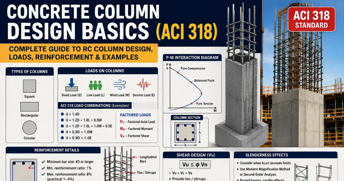
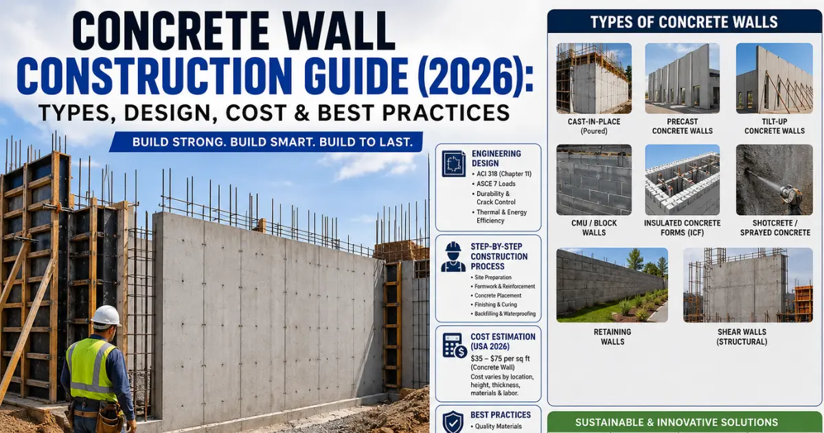
Concrete Column Design Basics (ACI 318): Complete Guide to RC Column Design, Loads, Reinforcement & Examples

Concrete Column Design Basics (ACI 318): Complete Guide to RC Column Design, Loads, Reinforcement & Examples

Concrete columns are one of the most important structural elements in any building. They are vertical load-bearing members designed to transfer loads safely from the slabs, beams, and roofs down to the foundation. A properly designed column primarily resists axial compression, but it can also withstand bending moments, shear forces, and in some cases torsional loads caused by wind, earthquakes, or uneven loading. Without strong and properly designed columns, a building cannot maintain its structural integrity or safely support its intended loads. Concrete Calculator

In residential, commercial, and industrial construction, concrete columns play a critical role in ensuring safety, stability, and durability. They provide the main load path for the structure, preventing excessive settlement, cracking, or structural failure. Well-designed columns improve a building’s ability to resist gravity loads, lateral forces, and long-term environmental effects, making them one of the most essential components of reinforced concrete construction.

Concrete columns come in several types depending on their geometry, reinforcement details, and structural behavior. The most common classifications include:

  • Short Columns – Designed with a low slenderness ratio and primarily fail due to concrete crushing under compression.
  • Slender Columns – Taller columns that are susceptible to buckling and require additional stability considerations during design.
  • Tied Columns – Reinforced with longitudinal bars enclosed by closed ties (hoops). These are the most commonly used columns in residential and commercial buildings throughout the United States.
  • Spiral Columns – Contain continuous spiral reinforcement that provides improved confinement, ductility, and seismic performance compared to tied columns.
  • Rectangular Columns – Widely used in buildings because they integrate easily with walls and beams.
  • Square Columns – Popular for residential structures due to their simple layout and balanced load distribution.
  • Circular Columns – Commonly used in bridges, parking garages, industrial facilities, and architectural applications where aesthetics or uniform load distribution is important.

Modern concrete column design in the United States follows the Strength Design approach, also known as Load and Resistance Factor Design (LRFD). Under this philosophy, engineers apply load factors to expected loads and reduce the nominal strength of structural members using strength reduction factors. This ensures that every column has an adequate safety margin against failure while remaining economical and efficient. The LRFD method accounts for uncertainties in material properties, construction quality, and loading conditions, making it the preferred design methodology for reinforced concrete structures.

The primary design standard for reinforced concrete columns in the United States is ACI 318 (Building Code Requirements for Structural Concrete). Developed and continuously updated by the American Concrete Institute, ACI 318 has evolved over decades through extensive research, laboratory testing, field performance, and lessons learned from real-world structures. Today, it serves as the foundation for concrete design across the U.S., providing engineers with comprehensive requirements for column sizing, reinforcement detailing, strength calculations, durability, serviceability, and seismic design. Its widespread adoption ensures consistent, reliable, and safe structural design practices across residential, commercial, and infrastructure projects.

Classification of Concrete Columns (ACI 318)

The American Concrete Institute ACI 318 code classifies reinforced concrete columns based on their slenderness, structural behavior, and reinforcement detailing. Understanding these classifications is essential because each type has different design requirements, load-carrying behavior, and stability considerations.

1. Short Columns vs. Slender Columns

One of the most important classifications in ACI 318 is whether a column behaves as a short column or a slender column.

Short Columns

A short column has a relatively small unsupported height compared to its cross-sectional dimensions. These columns primarily resist axial compression and bending moments, with minimal risk of buckling.

Characteristics include:

  • Higher load-carrying capacity
  • Buckling effects are generally insignificant
  • Simpler design calculations
  • Most common in low-rise residential and commercial buildings

When a column satisfies the ACI 318 slenderness limits, slenderness effects may be ignored, allowing engineers to use standard strength calculations without additional moment magnification.

Slender Columns

A slender column has a larger unsupported height relative to its cross-sectional size. Because of its geometry, it experiences additional bending due to buckling (second-order or P-Δ effects).

Characteristics include:

  • Lower stability than short columns
  • Additional bending moments caused by axial loads
  • Requires moment magnification or second-order analysis
  • Common in multi-story buildings and tall structures

Slenderness Ratio (kℓu/r)

ACI 318 evaluates column slenderness using the slenderness ratio:

kℓu​​/r

Where:

  • k = Effective length factor
  • ℓu = Unsupported column length
  • r = Radius of gyration of the column section

A larger kℓu/r value indicates a greater likelihood of buckling. If the calculated slenderness ratio remains within the ACI 318 limits, engineers can generally ignore slenderness effects. If the limits are exceeded, additional design procedures such as moment magnification or second-order analysis must be applied.

2. Braced vs. Unbraced Frames

ACI 318 also distinguishes columns based on the structural frame that supports them.

Braced Frames (Non-Sway Frames)

In a braced frame, lateral movement is restrained by structural elements such as:

  • Shear walls
  • Braced frames
  • Concrete cores

Characteristics:

  • Minimal lateral sway
  • Lower secondary moments
  • Higher overall stability
  • Simpler column design

Because lateral displacement is limited, columns in braced frames generally experience smaller additional bending moments.

Unbraced Frames (Sway Frames)

An unbraced frame allows noticeable lateral movement under wind or seismic loading.

Characteristics:

  • Larger lateral displacement
  • Greater second-order (P-Δ) effects
  • Increased bending moments
  • Requires more detailed stability analysis

Columns in sway frames must be designed carefully because lateral drift significantly influences their strength and serviceability.

3. Tied Columns vs. Spirally Reinforced Columns

ACI 318 classifies reinforced concrete columns according to their transverse reinforcement.

Tied Columns

A tied column contains longitudinal reinforcing bars enclosed by closed ties (hoops) placed at specified spacing.

Features include:

  • Most commonly used column type in the United States
  • Simple and economical construction
  • Suitable for residential, commercial, and industrial buildings
  • Provides adequate confinement for normal structural applications

Advantages:

  • Easy reinforcement placement
  • Lower construction cost
  • Widely accepted for standard building projects

Spirally Reinforced Columns

A spirally reinforced column uses continuous spiral reinforcement wrapped around the longitudinal bars.

Features include:

  • Continuous confinement of the concrete core
  • Improved ductility
  • Better energy absorption during earthquakes
  • Higher deformation capacity before failure

Advantages:

  • Superior confinement of concrete
  • Greater resistance to sudden brittle failure
  • Enhanced performance in seismic regions
  • Better post-yield behavior under heavy loading

Because spiral reinforcement provides more effective confinement than conventional ties, spirally reinforced columns generally offer better ductility and seismic performance, making them a preferred choice for bridges, high-rise buildings, and structures located in earthquake-prone areas.

Quick Comparison Table

ClassificationDescriptionTypical Application
Short ColumnLow slenderness ratio, buckling effects usually negligibleLow- and mid-rise buildings
Slender ColumnHigh slenderness ratio, buckling must be consideredHigh-rise buildings and tall structures
Braced FrameLateral movement restrained by shear walls or bracingBuildings with shear walls or concrete cores
Unbraced FrameFrame allowed to sway under lateral loadsMoment-resisting frame systems
Tied ColumnLongitudinal bars enclosed with closed tiesMost residential and commercial buildings
Spirally Reinforced ColumnContinuous spiral reinforcement around longitudinal barsBridges, seismic structures, and heavy-load applications

Materials Used in Concrete Column Design

The strength, durability, and long-term performance of a reinforced concrete column depend largely on the quality of its materials. According to American Concrete Institute ACI 318, engineers must select concrete and reinforcing steel that satisfy both structural strength and durability requirements. Proper material selection helps columns safely resist compression, bending, shear, and environmental exposure throughout the structure’s service life.

1. Concrete Compressive Strength (f’c)

The most important property of structural concrete is its specified compressive strength, denoted as f’c (pronounced “f-prime-c”). This value is typically measured at 28 days after casting and is expressed in pounds per square inch (psi) in the United States.

Higher compressive strength generally increases the load-carrying capacity of a column, although it may also affect stiffness, shrinkage, and cost.

Typical Concrete Strengths

Concrete Strength (f’c)Common Applications
3,000 psiLight residential construction
4,000 psiStandard residential foundations and columns
5,000 psiCommercial buildings and heavily loaded columns
6,000 psiMulti-story buildings and parking structures
8,000 psi and aboveHigh-rise buildings, bridges, and special structures

For most residential and commercial buildings in the U.S., 4,000 psi and 5,000 psi concrete are the most commonly specified strengths.

2. Reinforcing Steel Yield Strength (fy)

Concrete performs exceptionally well in compression but is relatively weak in tension. To resist tensile stresses and improve ductility, reinforced concrete columns contain steel reinforcing bars (rebar).

The strength of reinforcing steel is measured by its yield strength (fy).

Common Reinforcing Steel Grades

Steel GradeYield Strength
Grade 4040 ksi (40,000 psi)
Grade 6060 ksi (60,000 psi)
Grade 8080 ksi (used in specialized projects)

Grade 60 (60 ksi) reinforcing steel is the standard choice for most reinforced concrete buildings in the United States because it provides an excellent balance of strength, ductility, availability, and cost.

Steel reinforcement in columns consists of:

  • Longitudinal reinforcing bars
  • Ties (hoops) or spiral reinforcement
  • Properly anchored lap splices and development lengths

3. Modulus of Elasticity and Stress-Strain Behavior

Modulus of Elasticity (Ec)

The modulus of elasticity represents the stiffness of concrete and indicates how much it deforms under load.

Important characteristics include:

  • Higher-strength concrete generally has a higher modulus of elasticity.
  • Stiffer concrete experiences less elastic deformation under service loads.
  • The modulus of elasticity is used when calculating column deflection, stiffness, and second-order effects.

Stress-Strain Behavior of Concrete

Concrete exhibits a nonlinear stress-strain relationship.

Key characteristics:

  • Initially behaves almost linearly under small loads.
  • Reaches maximum compressive stress at approximately 0.003 compressive strain, which is commonly used in ACI 318 design.
  • After reaching peak strength, concrete gradually loses its load-carrying capacity as crushing begins.

Stress-Strain Behavior of Reinforcing Steel

Reinforcing steel behaves differently from concrete.

Its behavior includes:

  • Linear elastic response up to the yield point.
  • Yielding occurs at the specified fy value.
  • After yielding, steel undergoes significant plastic deformation before fracture.

This ductile behavior allows reinforced concrete columns to provide warning before failure and improves structural safety during extreme loading events.

4. Durability Requirements

In addition to strength, ACI 318 places significant emphasis on durability so that concrete columns can maintain their performance throughout their intended service life.

Concrete Cover

Concrete cover is the minimum thickness of concrete placed between the reinforcing steel and the exposed surface.

Adequate cover provides:

  • Protection against corrosion of reinforcement
  • Improved fire resistance
  • Better bond between concrete and steel
  • Increased durability in harsh environments

Required cover depends on factors such as:

  • Indoor or outdoor exposure
  • Contact with soil
  • Weather conditions
  • Marine or coastal environments
  • Exposure to deicing chemicals

Exposure Classes

ACI 318 defines exposure classes to ensure concrete mixtures and detailing are appropriate for environmental conditions.

Common exposure categories include:

Exposure ClassPrimary Concern
FFreeze-thaw cycles
SSulfate exposure
WWater exposure and permeability
CCorrosion caused by chlorides (such as deicing salts or seawater)

Each exposure class may require adjustments to:

  • Minimum concrete strength
  • Water-cement ratio
  • Air entrainment
  • Cementitious materials
  • Concrete cover thickness

Meeting these durability requirements helps minimize cracking, corrosion, and deterioration, allowing reinforced concrete columns to perform safely for decades with reduced maintenance.

Loads and Load Combinations

Concrete columns are designed to safely resist all loads that may act on a structure during its service life. According to American Concrete Institute ACI 318, the design of reinforced concrete columns follows the Strength Design (Load and Resistance Factor Design – LRFD) approach. In this method, actual loads are multiplied by load factors to account for uncertainties, ensuring that the column has sufficient strength and an appropriate margin of safety.

Types of Structural Loads

1. Dead Load (D)

Dead load (D) is the permanent weight of all structural and fixed non-structural components of a building. These loads remain relatively constant throughout the life of the structure.

Typical dead loads include:

  • Concrete slabs
  • Beams and columns
  • Walls and partitions
  • Roofing materials
  • Floor finishes
  • Mechanical and electrical equipment permanently attached to the building

Dead load is generally the largest sustained load acting on a concrete column.

2. Live Load (L)

Live load (L) consists of movable or temporary loads that vary over time depending on how the building is used.

Examples include:

  • Occupants
  • Furniture
  • Office equipment
  • Storage materials
  • Movable machinery

Unlike dead loads, live loads are not always present at their maximum value, but they must still be considered in structural design to ensure adequate safety.

3. Wind Load (W)

Wind load (W) acts laterally on a structure and can produce significant bending moments in columns, especially in taller buildings.

Wind loads depend on factors such as:

  • Building height
  • Geographic wind speed
  • Terrain and surrounding structures
  • Building shape
  • Exposure category

Wind loading can increase axial forces while also generating additional bending moments that must be included in column design.

4. Seismic Load (E)

Seismic load (E) represents earthquake forces acting on a structure.

During an earthquake, columns experience:

  • Lateral forces
  • Dynamic loading
  • Reversed bending moments
  • Increased shear forces
  • Additional axial load variations

Structures located in seismic regions require special detailing to improve ductility and energy dissipation, allowing columns to perform safely during earthquake events.

5. Other Possible Loads

Depending on the project, engineers may also consider additional loads, including:

  • Snow loads
  • Rain loads
  • Soil and earth pressure
  • Hydrostatic pressure
  • Impact loads
  • Construction loads
  • Temperature and shrinkage effects

Although not every project includes these loads, they may govern the design in certain structures or environmental conditions.zz

ACI Load Combinations

ACI 318 uses factored load combinations to evaluate the most critical loading scenarios a column may experience. These combinations increase the applied loads using prescribed load factors to account for uncertainties in loading conditions and material behavior.

Some common LRFD load combinations include:

  • U = 1.4D
  • U = 1.2D + 1.6L + 0.5(Lr or S or R)
  • U = 1.2D + 1.0W + L + 0.5(Lr or S or R)
  • U = 1.2D + 1.0E + L
  • U = 0.9D + 1.0W
  • U = 0.9D + 1.0E

Where:

  • U = Required factored load
  • D = Dead load
  • L = Live load
  • W = Wind load
  • E = Earthquake (seismic) load
  • Lr = Roof live load
  • S = Snow load
  • R = Rain load

The governing load combination is the one that produces the highest demand on the column and is used for final design.

Factored Design Forces

After applying the required load combinations, engineers calculate the factored design forces used to verify the strength of the column.

Factored Axial Load (Pu)

Pu is the factored axial compressive load acting on the column after applying the appropriate load combinations.

It is used to:

  • Determine the required column size
  • Calculate longitudinal reinforcement
  • Evaluate compression capacity

Factored Bending Moment (Mu)

Mu is the factored bending moment resulting from eccentric loading, wind, earthquakes, or frame action.

It is used to:

  • Check flexural strength
  • Design reinforcement layout
  • Develop axial load–moment (P–M) interaction diagrams

Factored Shear Force (Vu)

Vu is the factored shear force acting on the column.

Although columns are primarily compression members, they must also resist shear caused by:

  • Lateral loads
  • Beam reactions
  • Earthquakes
  • Wind forces

The shear capacity of the column is verified by considering both the concrete contribution and the transverse reinforcement (ties or spiral reinforcement).

Summary Table

SymbolDescriptionTypical Purpose
DDead LoadPermanent structural weight
LLive LoadOccupancy and movable loads
WWind LoadLateral wind effects
ESeismic LoadEarthquake forces
UFactored Load CombinationLRFD design load
PuFactored Axial LoadCompression design
MuFactored Bending MomentFlexural design
VuFactored Shear ForceShear design

By evaluating all applicable loads and applying the required ACI 318 load combinations, engineers can design reinforced concrete columns that safely resist both everyday service conditions and extreme loading events while maintaining structural reliability and code compliance.

Preliminary Sizing and Design Steps

Before performing detailed structural calculations, engineers establish the preliminary size of a concrete column. This initial sizing ensures that the column has sufficient strength, stiffness, and space for reinforcement while meeting the requirements of American Concrete Institute ACI 318. After selecting a preliminary section, the column is verified through detailed strength, stability, and serviceability checks.

1. Select Minimum Column Dimensions

The first step is choosing an appropriate column size based on the building type, loading conditions, architectural constraints, and applicable code requirements.

For cast-in-place reinforced concrete buildings, a minimum column dimension of approximately 12 inches (305 mm) is commonly used in practice. Larger buildings or heavily loaded columns generally require larger cross-sections.

Typical preliminary sizes include:

Column SizeCommon Applications
12″ × 12″Light residential construction
12″ × 16″Small commercial buildings
16″ × 16″Multi-story buildings
18″ × 18″ or largerHigh-load columns and taller structures

The selected dimensions should also provide adequate space for reinforcing bars, concrete placement, and proper concrete consolidation.

2. Calculate Gross Cross-Sectional Area (Ag)

The gross cross-sectional area (Ag) is the total area of the concrete section before subtracting the reinforcing steel.

For rectangular columns:

Ag = Width × Depth

Example:

  • Column size = 16 in × 16 in
  • Ag = 16 × 16 = 256 in²

The gross area is used in many ACI 318 design calculations, including:

  • Axial load capacity
  • Reinforcement ratio
  • Strength checks
  • Interaction diagram development

3. Select Reinforcement Ratio (ρ)

After determining the column dimensions, engineers estimate the amount of longitudinal reinforcement required.

The reinforcement ratio (ρ) is defined as:

ρ = Ast / Ag

Where:

  • ρ = Reinforcement ratio
  • Ast = Total area of longitudinal reinforcing steel
  • Ag = Gross cross-sectional area

ACI 318 Reinforcement Limits

RequirementReinforcement Ratio
Minimum1%
Maximum (Code Limit)8%
Practical Design Range1%–4%

Using reinforcement within the 1% to 4% practical range offers several advantages:

  • Easier concrete placement
  • Better consolidation around reinforcing bars
  • Improved constructability
  • Reduced reinforcement congestion
  • More economical construction

Although ACI 318 permits reinforcement ratios up to 8%, such high percentages are rarely used because they make concrete placement and vibration much more difficult.

4. Provide Adequate Clear Cover

Clear cover is the minimum distance between the outer surface of the concrete and the nearest reinforcing steel.

Proper concrete cover is essential for:

  • Corrosion protection
  • Fire resistance
  • Long-term durability
  • Proper bond between concrete and reinforcement

For interior cast-in-place columns, a typical clear cover of 1.5 inches (38 mm) is commonly provided.

Greater cover may be required for columns exposed to:

  • Outdoor weather
  • Soil contact
  • Marine environments
  • Deicing salts
  • Severe environmental conditions
  • Fire-resistance requirements

Increasing concrete cover improves durability but should be balanced with structural detailing and reinforcement placement requirements.

Typical Preliminary Design Workflow

Engineers generally follow these basic steps during preliminary column sizing:

  1. Determine the factored loads acting on the column.
  2. Select an initial column size based on expected loading and architectural constraints.
  3. Calculate the gross cross-sectional area (Ag).
  4. Estimate the required longitudinal reinforcement while maintaining a reinforcement ratio between 1% and 4% (within the ACI 318 limits of 1% to 8%).
  5. Provide the required clear cover and arrange reinforcing bars with adequate spacing.
  6. Perform detailed strength, slenderness, interaction, and serviceability checks to confirm the final design.

Quick Reference Table

Design ParameterTypical Recommendation
Minimum Cast-in-Place Column Dimension12 in (305 mm)
Gross Area (Ag)Width × Depth
Minimum Reinforcement Ratio (ρ)1%
Maximum Reinforcement Ratio (ACI 318)8%
Practical Reinforcement Ratio1%–4%
Typical Interior Clear Cover1.5 in (38 mm)
Exterior/Exposed ColumnsIncreased cover based on exposure conditions

Establishing appropriate preliminary dimensions, reinforcement ratios, and concrete cover provides a solid foundation for detailed structural design. These initial decisions help ensure that reinforced concrete columns are strong, durable, constructible, and compliant with ACI 318 requirements while minimizing unnecessary material costs.

Axial Load Capacity (Pure Compression)

The primary function of a reinforced concrete column is to resist axial compression while safely transferring loads from the structure above to the foundation. In many practical situations, columns are also subjected to bending moments and shear forces. However, understanding the pure compression capacity is the first step in reinforced concrete column design. According to American Concrete Institute ACI 318, the axial strength of a short column depends on the strength of both the concrete and the reinforcing steel.

Nominal Axial Strength (Pn)

The nominal axial strength (Pn) represents the theoretical compression capacity of a reinforced concrete column before applying any strength reduction factors.

For a concentrically loaded reinforced concrete column:

Pn​=0.85fc′​(Ag−Ast​)+fy​Ast​

Where:

  • Pn = Nominal axial strength
  • f’c = Specified concrete compressive strength
  • Ag = Gross cross-sectional area
  • Ast = Total area of longitudinal reinforcement
  • fy = Yield strength of reinforcing steel

The first term represents the load carried by the concrete, while the second term represents the contribution of the reinforcing steel.

Strength Reduction Factors (φ)

ACI 318 uses strength reduction factors (φ) to account for uncertainties in materials, construction quality, and loading conditions.

Tied Columns

For columns reinforced with closed ties:

  • φ = 0.65

Design strength:

ϕPn​=0.65Pn​

Spirally Reinforced Columns

For columns with continuous spiral reinforcement:

  • φ = 0.75

Design strength:

ϕPn​=0.75Pn​

Because spiral reinforcement provides better confinement of the concrete core, spirally reinforced columns receive a higher strength reduction factor than tied columns.

Maximum Axial Load Limits

ACI 318 limits the usable axial design strength for concentrically loaded columns to provide an additional safety margin and account for unavoidable construction imperfections and load eccentricities.

Tied Columns

Maximum usable axial load:

Pu​≤0.80ϕPn,max​

This means the factored axial load should not exceed 80% of the design axial strength.

Spirally Reinforced Columns

Maximum usable axial load:

Pu​≤0.85ϕPn,max​

Because spiral reinforcement improves confinement and ductility, ACI 318 permits 85% of the design axial strength to be used.

Comparison of Design Factors

Column TypeStrength Reduction Factor (φ)Maximum Usable Axial Strength
Tied Column0.650.80φPn,max
Spiral Column0.750.85φPn,max

Example Calculation

Consider a short tied reinforced concrete column with the following properties:

  • Concrete strength, f’c = 4,000 psi
  • Steel yield strength, fy = 60,000 psi
  • Column size = 16 in × 16 in
  • Gross area, Ag = 256 in²
  • Total reinforcement area, Ast = 4.00 in²

Step 1: Calculate Nominal Axial Strength

Concrete contribution:

0.85×4000×(256−4)=856,800 lb

Steel contribution:

60,000×4=240,000 lb

Nominal axial strength:

Pn​=856,800+240,000=1,096,800 lb

Pn​≈1,097 kips

Step 2: Apply Strength Reduction Factor

For a tied column:

ϕPn​=0.65×1,096,800=712,920 lb

ϕPn​≈713 kips

Step 3: Determine Maximum Permitted Axial Load

ACI 318 limits the usable strength for tied columns to:

0.80×713=570 kips

Therefore, the maximum factored axial load permitted for this example is approximately:

Pu≈570 kips

Important Design Notes

  • The equations above apply primarily to short columns under concentric (pure axial) compression.
  • Real building columns almost always experience some load eccentricity, producing combined axial compression and bending.
  • Slender columns require additional checks for second-order (P–Δ) effects.
  • Final design should also verify reinforcement detailing, clear cover, confinement, shear capacity, and load combinations in accordance with ACI 318.

Understanding the nominal axial strength (Pn) and the applicable strength reduction factors (φ) provides the foundation for reinforced concrete column design. These calculations help engineers ensure that columns can safely resist factored loads while maintaining the required safety margins and structural reliability.

Combined Axial Load + Bending (Most Common Design Case)

In real-world buildings, reinforced concrete columns rarely experience pure axial compression. Most columns are subjected to a combination of axial load (Pu) and bending moment (Mu) due to beam reactions, eccentric loading, wind, earthquakes, and frame action. This condition is known as combined axial load and bending, and it is the most common design scenario addressed by American Concrete Institute ACI 318.

Because both compression and bending act simultaneously, engineers must verify that the column has sufficient capacity to resist the combined effects rather than checking each force independently.

Interaction Diagram (P-M Diagram)

The primary design tool for evaluating combined loading is the Axial Load–Moment Interaction Diagram (P-M Diagram).

A P-M diagram illustrates the relationship between:

  • Axial Load (P)
  • Bending Moment (M)

Each point on the interaction curve represents a safe combination of axial load and bending moment that the column can resist.

General interpretation:

  • Points inside the curve → Safe design
  • Points on the curve → Maximum design capacity
  • Points outside the curve → Unsafe (column must be redesigned)

The P-M interaction diagram is one of the most important tools used in reinforced concrete column design because it accounts for the combined behavior of concrete and reinforcing steel under different loading conditions.

Control Points on the Interaction Curve

Several important points define the shape of the interaction diagram.

1. Pure Compression

At the top of the interaction curve:

  • Maximum axial load
  • Negligible bending moment
  • Entire cross-section is in compression

This condition represents the theoretical maximum compression capacity of the column.

2. Balanced Point

The balanced point occurs when:

  • Concrete reaches its ultimate compressive strain.
  • Tensile reinforcement reaches its yield strength at the same time.

This point separates two different failure modes:

  • Compression-controlled behavior
  • Tension-controlled behavior

It is one of the most significant locations on the interaction diagram because it marks the transition between brittle and ductile structural behavior.

3. Pure Tension

At the opposite end of the interaction curve:

  • Axial compression becomes zero.
  • Reinforcing steel carries nearly all the applied force.
  • Concrete contributes very little because it has low tensile strength.

Although pure tension is uncommon in typical building columns, it is included to define the complete interaction relationship.

Load Eccentricity

Combined loading occurs because the applied load is rarely perfectly centered on the column.

The eccentricity (e) is calculated as:

e=Pu​/Mu​​

Where:

  • e = Load eccentricity
  • Mu = Factored bending moment
  • Pu = Factored axial load

A larger eccentricity produces:

  • Greater bending stresses
  • Lower axial load capacity
  • Increased reinforcement demand

Even small construction tolerances or beam framing can introduce eccentricity, which is why ACI 318 generally assumes that practical columns experience some degree of bending.

Strain Compatibility Method

ACI 318 evaluates column strength using the strain compatibility method.

This method assumes:

  • Plane sections remain plane after bending.
  • Concrete and reinforcing steel deform together.
  • Strain varies linearly across the cross-section.

Using the strain distribution, engineers calculate:

  • Concrete compression force
  • Steel compression force
  • Steel tension force

The internal forces are then balanced to determine the column’s axial and moment capacities.

The strain compatibility method forms the basis for generating accurate P-M interaction diagrams.

Whitney Stress Block

To simplify compression calculations, ACI 318 uses the Whitney Rectangular Stress Block.

Its main assumptions are:

  • Concrete compression stress is represented by a uniform rectangular block.
  • Average compressive stress equals 0.85f’c.
  • The equivalent compression block depth is determined using ACI 318 parameters.

The concrete compression force is expressed as:

C=0.85fc′​×b×a

Where:

  • C = Concrete compression force
  • 0.85f’c = Equivalent concrete stress
  • b = Width of compression zone
  • a = Depth of the equivalent rectangular stress block

The Whitney stress block greatly simplifies hand calculations while providing results that closely match the actual nonlinear behavior of reinforced concrete.

Uniaxial vs. Biaxial Bending

Columns may bend about one axis or two axes simultaneously.

Uniaxial Bending

Uniaxial bending occurs when the bending moment acts about only one principal axis.

Characteristics include:

  • Simpler analysis
  • Standard P-M interaction diagram is generally sufficient
  • Common in beams framing into one direction

Examples:

  • Rectangular columns subjected to bending only about the strong axis
  • Wall-supported columns with one primary bending direction

Biaxial Bending

Biaxial bending occurs when moments act simultaneously about both principal axes.

Characteristics include:

  • More complex stress distribution
  • Reduced load-carrying capacity
  • Requires biaxial interaction analysis or specialized design software
  • Common in corner columns and columns subjected to wind or seismic forces from multiple directions

Because columns in modern buildings often experience multidirectional loading, biaxial bending is frequently considered during final structural design.

Summary Table

Design ConceptDescription
P-M Interaction DiagramPrimary tool for evaluating combined axial load and bending capacity
Pure Compression PointMaximum axial capacity with little or no bending
Balanced PointConcrete reaches ultimate compression while tensile steel yields simultaneously
Pure Tension PointReinforcing steel resists nearly all applied force
Eccentricity (e = Mu/Pu)Measures how far the load acts from the column’s centroid
Strain Compatibility MethodCalculates internal forces based on linear strain distribution
Whitney Stress BlockUses a rectangular compression block with 0.85f’c to simplify concrete compression analysis
Uniaxial BendingBending about one principal axis
Biaxial BendingSimultaneous bending about both principal axes requiring more advanced analysis

By combining axial load, bending moments, strain compatibility, and the P-M interaction diagram, engineers can accurately determine whether a reinforced concrete column satisfies ACI 318 strength requirements. This comprehensive approach ensures that columns remain safe, stable, and capable of supporting complex loading conditions encountered in modern buildings.

Shear Design in Columns

Although reinforced concrete columns are primarily designed to resist axial compression and bending moments, they must also have adequate capacity to resist shear forces. Shear forces commonly develop due to wind loads, earthquake forces, beam reactions, frame action, and unbalanced loading. If shear is not properly addressed, a column can experience a sudden and brittle failure. Therefore, American Concrete Institute ACI 318 requires every reinforced concrete column to be checked for shear strength and provided with sufficient transverse reinforcement.

Factored Shear Force (Vu)

The first step in shear design is determining the factored shear force (Vu) obtained from the governing load combinations.

Where:

  • Vu = Factored shear force acting on the column

The design requirement is:

Vu​≤ϕVn​

Where:

  • Vu = Factored shear demand
  • Vn = Nominal shear strength of the column
  • φ = Strength reduction factor for shear (as specified by ACI 318)

The nominal shear strength consists of:

  • Concrete contribution (Vc)
  • Shear reinforcement contribution (Vs)

Therefore:

Vn​=Vc​+Vs​

If the applied shear force exceeds the concrete’s shear capacity alone, additional transverse reinforcement must be provided.

Shear Reinforcement (Stirrups or Ties)

Concrete columns use transverse reinforcement, commonly called ties (or stirrups in some applications), to resist shear and improve overall structural performance.

The primary functions of shear reinforcement are:

  • Resist shear forces
  • Hold longitudinal reinforcing bars in their proper position
  • Confine the concrete core
  • Prevent buckling of longitudinal reinforcement under compression
  • Improve ductility, particularly during seismic events

Tied Columns

In tied columns, closed steel ties are placed around the longitudinal reinforcing bars at regular intervals.

Advantages include:

  • Increased shear resistance
  • Better confinement of concrete
  • Improved structural stability
  • Easier reinforcement placement during construction

Spiral Columns

Instead of individual ties, spiral columns use a continuous spiral reinforcement wrapped around the longitudinal bars.

Compared with tied columns, spiral reinforcement provides:

  • Better confinement of the concrete core
  • Improved ductility
  • Higher energy absorption
  • Superior performance during earthquakes and cyclic loading

Spacing Requirements for Ties

ACI 318 specifies maximum spacing limits for transverse reinforcement to ensure adequate confinement and shear resistance.

The spacing of ties should not exceed the smallest of the following:

  • 16 times the diameter of the smallest longitudinal reinforcing bar
  • 48 times the diameter of the tie (transverse reinforcement) bar
  • The least dimension of the column cross-section

These limits help ensure that:

  • Longitudinal bars remain laterally supported.
  • Concrete is effectively confined.
  • Shear cracks are controlled.
  • Compression reinforcement does not buckle.

In regions of high seismic activity or near beam-column joints, ACI 318 often requires closer tie spacing to enhance confinement and improve the column’s ductile behavior under cyclic loading.

Typical Shear Design Procedure

Engineers generally follow these steps when designing column shear reinforcement:

  1. Calculate the factored shear force (Vu) from the governing load combinations.
  2. Determine the nominal shear strength (Vn = Vc + Vs).
  3. Verify that Vu ≤ φVn.
  4. Design the required transverse reinforcement if additional shear capacity is needed.
  5. Check that tie spacing complies with ACI 318 maximum spacing requirements.
  6. Confirm proper detailing, including tie anchorage, corner bar restraint, and seismic confinement where applicable.

Summary Table

Design ParameterDescription
VuFactored shear force acting on the column
Design CheckVu ≤ φVn
Nominal Shear Strength (Vn)Vc + Vs (concrete contribution + reinforcement contribution)
Shear ReinforcementClosed ties (stirrups) or continuous spiral reinforcement
Functions of TiesResist shear, confine concrete, support longitudinal bars, prevent bar buckling
Maximum Tie SpacingLesser of 16db (longitudinal bar), 48db (tie bar), or least column dimension
Seismic RegionsCloser tie spacing is typically required for improved confinement and ductility

Proper shear design is essential for the safe performance of reinforced concrete columns. By checking Vu, providing adequate transverse reinforcement, and complying with ACI 318 tie spacing requirements, engineers can ensure that columns remain stable, ductile, and capable of resisting both everyday service loads and extreme events such as strong winds and earthquakes.

Detailing Requirements (Critical for USA Practice)

Proper detailing is just as important as strength calculations in reinforced concrete column design. Even if a column has adequate theoretical capacity, poor reinforcement detailing can significantly reduce its performance during heavy loading, wind, or earthquakes. For this reason, American Concrete Institute ACI 318 provides comprehensive detailing requirements covering reinforcement placement, tie spacing, lap splices, development length, and seismic reinforcement. Correct detailing ensures that columns remain strong, ductile, durable, and constructible throughout their service life.

Longitudinal Reinforcement Arrangement

Longitudinal reinforcement consists of the vertical reinforcing bars that carry axial compression and bending forces.

General ACI 318 detailing guidelines include:

  • Reinforcing bars should be distributed as uniformly as possible around the perimeter of the column.
  • Bars should be positioned symmetrically to improve strength under bending from different directions.
  • Corner bars must be enclosed and restrained by ties or spiral reinforcement.
  • Interior bars should also be adequately supported by transverse reinforcement.

Minimum Bar Size

For reinforced concrete columns, the longitudinal reinforcement should generally consist of No. 3 (#3) bars or larger, although No. 5 (#5), No. 6 (#6), and No. 8 (#8) bars are far more common in structural columns due to their greater strength and practical constructability.

Typical minimum number of longitudinal bars:

Column ShapeMinimum Longitudinal Bars
Rectangular or Square4 bars
Circular (Tied)6 bars
Spiral Columns6 bars or more

Tie (Stirrup) Size and Spacing

Transverse reinforcement, commonly called ties or stirrups, serves several important functions:

  • Resists shear forces
  • Confines the concrete core
  • Prevents buckling of longitudinal bars
  • Maintains reinforcement alignment during concrete placement

Tie Size

ACI 318 generally requires ties to be No. 3 (#3) bars or larger. Larger tie sizes may be necessary for heavily reinforced columns or larger longitudinal reinforcement.

Maximum Tie Spacing

The vertical spacing of ties should not exceed the smallest of the following limits:

  • 16 × db (diameter of the smallest longitudinal reinforcing bar)
  • 48 × db (diameter of the tie bar)
  • Least dimension of the column cross-section

In addition, many designers use the practical guideline of keeping tie spacing no greater than approximately one-quarter of the least column dimension in critical regions to improve confinement, particularly where higher ductility is desired.

Closer tie spacing provides:

  • Better confinement
  • Improved shear resistance
  • Increased ductility
  • Greater earthquake performance

Lap Splices

When reinforcing bars cannot be supplied in a single continuous length, they must be connected using lap splices or mechanical couplers.

ACI 318 requires lap splice lengths based on:

  • Concrete strength (f’c)
  • Steel yield strength (fy)
  • Bar diameter
  • Concrete cover
  • Bar spacing
  • Reinforcement location

Good detailing practices include:

  • Locate lap splices away from regions of maximum stress whenever possible.
  • Avoid splicing all bars at the same location unless specifically permitted.
  • Stagger lap splices to reduce reinforcement congestion and improve load transfer.
  • Ensure ties continue through splice regions to provide proper confinement.

Development Length

The development length (Ld) is the minimum embedment length required for a reinforcing bar to fully develop its yield strength through bond with the surrounding concrete.

Development length depends on factors such as:

  • Bar size
  • Concrete compressive strength
  • Steel yield strength
  • Concrete cover
  • Bar coating (epoxy-coated or uncoated)
  • Confinement provided by transverse reinforcement

Providing adequate development length ensures:

  • Efficient force transfer between steel and concrete
  • Prevention of bond failure
  • Reliable structural performance under design loads

Seismic Detailing (ACI 318 Chapter 18)

For structures located in earthquake-prone regions, ACI 318 Chapter 18 introduces additional detailing requirements to improve ductility and energy dissipation.

Typical seismic detailing provisions include:

  • Reduced tie spacing in plastic hinge regions
  • Continuous confinement reinforcement near beam-column joints
  • 135° seismic hooks on transverse reinforcement
  • Increased confinement at column ends
  • Proper anchorage of longitudinal bars
  • Strong-column/weak-beam design philosophy
  • Enhanced detailing to prevent brittle failure during cyclic loading

These requirements enable reinforced concrete columns to withstand repeated inelastic deformation while maintaining structural integrity during major earthquakes.

Bar Placement and Bundling

Correct placement of reinforcing bars is essential for both structural performance and concrete quality.

Bar Placement

ACI 318 requires that reinforcement be placed so that:

  • Adequate concrete cover is maintained.
  • Bars have sufficient clear spacing for concrete flow and consolidation.
  • Reinforcement does not interfere with proper vibration during placement.
  • Congestion is minimized to reduce honeycombing and voids.

Proper bar placement improves bond, durability, and overall constructability.

Bundling Limits

In heavily loaded columns, reinforcing bars may sometimes be grouped into bundles.

Important considerations include:

  • Bundled bars should comply with ACI 318 detailing provisions.
  • Bundles should not create excessive reinforcement congestion.
  • Additional confinement may be required around bundled reinforcement.
  • Proper concrete consolidation around bundled bars must be ensured.
  • Mechanical couplers may be preferred over excessive bundling in heavily reinforced columns.

Although bundling can simplify reinforcement placement in large columns, excessive bundling may reduce concrete quality and make construction more difficult.

Summary Table

Detailing RequirementTypical ACI 318 Practice
Minimum Longitudinal Bar Size#3 bar or larger (larger bars commonly used in practice)
Minimum Number of Bars4 (rectangular/square), 6 (circular or spiral columns)
Tie Size#3 bar or larger
Maximum Tie SpacingLesser of 16db (longitudinal bar), 48db (tie bar), or least column dimension
Practical Critical-Region SpacingOften limited to about ¼ of the least column dimension for improved confinement where appropriate
Lap SplicesDesigned according to ACI 318 development and splice requirements
Development Length (Ld)Based on bar size, concrete strength, steel strength, cover, and confinement
Seismic DetailingFollow ACI 318 Chapter 18 with closer ties, 135° hooks, and enhanced confinement
Bar PlacementMaintain proper cover, spacing, and concrete consolidation
Bar BundlingPermitted within ACI 318 limits while avoiding excessive congestion

Proper detailing is one of the most critical aspects of reinforced concrete column design in the United States. By following ACI 318 requirements for longitudinal reinforcement, transverse ties, lap splices, development length, seismic detailing, and bar placement, engineers ensure that concrete columns achieve not only their calculated strength but also the ductility, durability, and reliability required for long-term structural performance.

Slenderness Effects

Not all reinforced concrete columns behave the same under load. While short columns primarily resist axial compression and bending without significant stability issues, slender columns are more susceptible to buckling and second-order (P–Δ) effects. As a column becomes taller relative to its cross-sectional dimensions, lateral deflections increase, creating additional bending moments that reduce its load-carrying capacity. For this reason, American Concrete Institute ACI 318 requires engineers to evaluate slenderness effects whenever they may significantly influence column behavior.

When Should Slenderness Effects Be Considered?

Slenderness effects should be considered when a column’s slenderness ratio (kℓu/r) exceeds the limits specified by ACI 318 or when second-order effects become significant.

Where:

  • k = Effective length factor
  • ℓu = Unsupported column length
  • r = Radius of gyration

A larger kℓu/r ratio indicates a greater tendency for the column to buckle under compression.

If the column satisfies the ACI 318 slenderness limits, engineers may generally ignore slenderness effects and design the column using first-order analysis. If the limits are exceeded, additional analysis is required to account for the increased bending caused by column deflection.

Typical situations where slenderness effects become important include:

  • Tall building columns
  • Multi-story structures
  • Long unsupported column heights
  • Columns carrying high axial loads
  • Flexible structural frames

Moment Magnification Method

For many practical building designs, ACI 318 permits the Moment Magnification Method to account for slenderness effects without performing a full nonlinear structural analysis.

The basic concept is straightforward:

  1. Calculate the first-order bending moment using conventional structural analysis.
  2. Determine the moment magnification factor based on column slenderness and axial loading.
  3. Multiply the first-order moment by this factor to obtain the magnified design moment.

The magnified moment reflects the additional bending caused by lateral deflection under load.

Advantages of the moment magnification method include:

  • Relatively simple calculations
  • Suitable for most low- and medium-rise buildings
  • Recognized by ACI 318
  • Eliminates the need for complex nonlinear analysis in many cases

Braced Frames vs. Sway Frames

The significance of slenderness effects depends greatly on whether the structure is braced or unbraced (sway).

Braced Frames (Non-Sway Frames)

In a braced frame, lateral movement is restrained by structural elements such as:

  • Shear walls
  • Braced frames
  • Concrete cores

Characteristics include:

  • Minimal lateral displacement
  • Smaller second-order effects
  • Reduced moment magnification
  • Higher structural stability

Because the frame resists lateral movement effectively, slenderness effects are generally less severe.

Sway Frames (Unbraced Frames)

In a sway frame, the structure is free to move laterally under wind or earthquake loading.

Characteristics include:

  • Larger lateral deflections
  • Greater P–Δ effects
  • Higher magnified bending moments
  • Increased sensitivity to instability

Columns in sway frames require more rigorous slenderness evaluation because the interaction between axial load and lateral displacement can significantly reduce their strength.

Approximate Methods

ACI 318 permits several approximate methods for evaluating slenderness effects in routine building design.

These methods generally involve:

  • Determining the effective length factor (k)
  • Evaluating the slenderness ratio (kℓu/r)
  • Applying moment magnification factors
  • Considering the stiffness of columns and beams
  • Accounting for axial load level

Approximate methods are appropriate when:

  • The building has regular geometry
  • Loading conditions are well defined
  • Structural behavior is reasonably predictable
  • The assumptions of ACI 318 are satisfied

These simplified procedures are widely used in everyday engineering practice because they provide accurate results for many common structures while reducing design complexity.

Second-Order Analysis

For more complex structures, ACI 318 allows or may require a second-order analysis.

Unlike first-order analysis, second-order analysis explicitly includes the effects of structural deformation on internal forces.

It accounts for:

  • P–Δ (global frame displacement) effects
  • P–δ (local member curvature) effects
  • Material stiffness
  • Geometric nonlinearity
  • Interaction between axial load and bending

Second-order analysis is commonly used for:

  • High-rise buildings
  • Slender columns
  • Flexible structural systems
  • Buildings subjected to large lateral loads
  • Performance-based seismic design

Although more computationally intensive, modern structural analysis software performs second-order analysis efficiently and provides more accurate predictions of column behavior under combined loading.

Practical Design Considerations

When designing slender reinforced concrete columns, engineers should:

  • Evaluate the column’s slenderness ratio.
  • Determine whether ACI 318 requires slenderness effects to be included.
  • Identify whether the structure is a braced or sway frame.
  • Apply the moment magnification method where permitted.
  • Use second-order analysis for taller or more complex structures.
  • Verify strength using the magnified moments and applicable load combinations.

Summary Table

Design AspectDescription
Slenderness CheckBased on the kℓu/r ratio to determine whether slenderness effects must be considered
Moment Magnification MethodSimplified ACI 318 procedure that increases first-order moments to account for second-order effects
Braced FrameLateral movement restrained; smaller slenderness effects
Sway FrameLateral movement permitted; larger P–Δ effects and greater moment magnification
Approximate MethodsSimplified calculations using effective length and magnification factors for routine designs
Second-Order AnalysisAdvanced analysis that directly includes deformation effects, geometric nonlinearity, and stability

Considering slenderness effects is essential for ensuring the safety and stability of reinforced concrete columns. By applying the appropriate ACI 318 procedures—whether through the moment magnification method or second-order analysis—engineers can accurately account for additional bending caused by column deflection and design structures that remain reliable under both gravity and lateral loading.

Special Considerations

In addition to strength calculations and reinforcement detailing, successful concrete column design requires attention to durability, constructability, design tools, and quality control. These factors significantly influence the long-term performance of reinforced concrete columns and help ensure compliance with American Concrete Institute ACI 318. Proper planning during the design and construction phases reduces maintenance costs, improves structural reliability, and minimizes the risk of construction errors.

1. Corrosion Protection

Corrosion of reinforcing steel is one of the leading causes of deterioration in reinforced concrete structures. When steel corrodes, it expands, causing cracking, spalling, and loss of structural capacity.

Effective corrosion protection includes:

  • Providing the required concrete cover around reinforcement.
  • Using low-permeability, high-quality concrete with an appropriate water-cement ratio.
  • Following ACI 318 durability requirements for the applicable exposure class.
  • Ensuring proper concrete consolidation to eliminate honeycombs and voids.
  • Using epoxy-coated, galvanized, or stainless-steel reinforcement where severe corrosion exposure is expected.
  • Protecting columns exposed to seawater, deicing salts, or aggressive chemicals with suitable materials and detailing.
  • Performing regular inspections and maintenance to identify early signs of deterioration.

Proper corrosion protection greatly extends the service life of reinforced concrete columns and reduces long-term repair costs.

2. Constructability

A structurally sound design must also be practical to construct. Good constructability improves construction quality, reduces labor costs, and minimizes delays.

Formwork

Proper formwork is essential for maintaining the designed column dimensions and alignment.

Good formwork should:

  • Be strong enough to resist fresh concrete pressure.
  • Maintain accurate column dimensions.
  • Prevent leakage of cement paste.
  • Be properly braced to avoid movement during concrete placement.
  • Produce smooth, defect-free concrete surfaces.

Concrete Placement

Correct concrete placement is equally important.

Best practices include:

  • Place concrete continuously whenever possible.
  • Avoid excessive free-fall that may cause segregation.
  • Consolidate concrete using mechanical vibration.
  • Ensure concrete flows completely around reinforcement.
  • Prevent reinforcement displacement during pouring.
  • Cure the concrete adequately to achieve the specified strength and durability.

Proper placement and consolidation help eliminate voids, honeycombing, and weak zones that can reduce column strength.

3. Software Tools for Column Design

Modern structural engineering relies heavily on specialized software to improve accuracy and efficiency.

Common software applications can:

  • Generate P–M (Axial Load–Moment) Interaction Diagrams.
  • Perform uniaxial and biaxial column analysis.
  • Evaluate slenderness and second-order effects.
  • Check reinforcement ratios and detailing.
  • Verify compliance with ACI 318 design provisions.
  • Produce design reports and reinforcement schedules.

Many commercial structural analysis and reinforced concrete design programs include built-in tools for column design, allowing engineers to evaluate multiple design alternatives quickly while reducing calculation errors.

Although software greatly improves productivity, engineering judgment remains essential. Designers should always verify that software assumptions, input parameters, and results are consistent with project requirements and applicable building codes.

4. Common Mistakes to Avoid

Many column design problems arise from incorrect assumptions or inadequate detailing rather than complex calculations.

Common mistakes include:

  • Ignoring slenderness effects in tall columns.
  • Underestimating wind or seismic loads.
  • Using insufficient longitudinal reinforcement.
  • Exceeding practical reinforcement ratios, causing reinforcement congestion.
  • Providing inadequate concrete cover for the exposure conditions.
  • Incorrect tie spacing or improper transverse reinforcement detailing.
  • Poor lap splice locations or insufficient development length.
  • Failing to account for load eccentricity and combined axial load with bending.
  • Inadequate concrete consolidation leading to honeycombing and voids.
  • Relying solely on software without independently reviewing the design.
  • Neglecting constructability, making reinforcement difficult to place or concrete difficult to consolidate.

Avoiding these common errors improves structural safety, simplifies construction, and enhances the long-term durability of reinforced concrete columns.

Best Practices for Reliable Column Design

To achieve safe and economical reinforced concrete columns, engineers should:

  • Select appropriate material strengths for the project.
  • Consider all applicable load combinations and second-order effects.
  • Provide adequate reinforcement and proper detailing.
  • Meet ACI 318 durability and cover requirements.
  • Ensure practical reinforcement layouts for easy construction.
  • Use structural design software to support—not replace—engineering judgment.
  • Coordinate closely with contractors during construction to maintain design quality.
  • Conduct thorough inspections during reinforcement placement and concrete casting.

Summary Table

Special ConsiderationImportance
Corrosion ProtectionPrevents reinforcement deterioration and extends service life
FormworkMaintains correct dimensions, alignment, and concrete quality
Concrete PlacementEnsures proper consolidation, strength, and durability
Software ToolsGenerate interaction diagrams, analyze columns, and verify ACI 318 compliance
Common MistakesInclude poor detailing, inadequate cover, ignoring slenderness, reinforcement congestion, and overreliance on software

By combining sound engineering principles with proper detailing, quality construction practices, and careful quality control, reinforced concrete columns can provide high strength, excellent durability, and reliable long-term performance. Addressing these special considerations helps ensure that columns not only satisfy ACI 318 design requirements but also perform safely and efficiently throughout the life of the structure.

Frequently Asked Questions (FAQs)

What is a concrete column?

A concrete column is a vertical structural member that transfers loads from slabs, beams, and roofs to the foundation. It primarily resists axial compression but is also designed to withstand bending moments and shear forces.

What is the difference between a short column and a slender column?

A short column has a low slenderness ratio and is mainly governed by material strength. A slender column has a higher slenderness ratio and requires additional analysis to account for buckling and second-order (P-Δ) effects.

What is the minimum reinforcement ratio for reinforced concrete columns?

According to ACI 318, the minimum longitudinal reinforcement ratio is 1% of the gross cross-sectional area, while the maximum permitted ratio is 8%. In practice, engineers typically use 1%–4% reinforcement for better constructability.

What is the minimum recommended size for a cast-in-place concrete column?

A 12-inch (305 mm) minimum dimension is commonly used for cast-in-place reinforced concrete columns, although the final size depends on structural loads, building height, and project requirements.

Concrete Wall Construction Guide (2026): Types, Design, Cost & Best Practices

Concrete Wall Construction Guide (2026): Types, Design, Cost & Best Practices

Concrete walls are one of the most reliable and durable building systems used in modern construction across the United States. Whether for residential homes, commercial buildings, or large infrastructure projects, they provide exceptional structural strength, long service life, and superior performance under demanding conditions. Compared with many other wall systems, properly designed concrete walls require minimal maintenance and can remain in excellent condition for decades. Concrete Calculator

One of the biggest advantages of concrete walls is their outstanding durability. They offer excellent fire resistance, helping improve building safety while meeting strict building code requirements. Their high thermal mass contributes to better energy efficiency by reducing indoor temperature fluctuations, which can lower heating and cooling costs. Concrete walls also provide excellent soundproofing, making them ideal for homes, offices, schools, and apartment buildings where noise reduction is important. In addition, reinforced concrete walls are designed to withstand natural disasters such as earthquakes, hurricanes, high winds, floods, and severe weather events, making them a preferred choice in many regions of the USA.

Concrete walls are widely used throughout the United States in both residential and commercial construction. Common applications include basement walls, foundation walls, retaining walls, privacy and boundary walls, parking structures, warehouses, industrial facilities, schools, hospitals, and modern tilt-up commercial buildings. Their versatility allows engineers and contractors to adapt concrete wall systems to projects of nearly every size and complexity.

When compared with alternative construction materials such as wood framing or traditional masonry, concrete walls offer several long-term advantages. They are highly resistant to rot, termites, moisture damage, and weathering while requiring significantly less maintenance over their lifespan. Although concrete wall construction generally involves a higher upfront investment and may require specialized labor and equipment, the long-term savings from increased durability, lower maintenance costs, and improved structural performance often make it a cost-effective solution.

This guide provides a complete overview of concrete wall construction in the USA. You’ll learn about the different types of concrete walls, materials and reinforcement, design considerations, step-by-step construction methods, insulation options, drainage requirements, building code compliance, safety practices, common mistakes to avoid, maintenance tips, and best practices to ensure a strong, durable, and code-compliant concrete wall.

Types of Concrete Walls

The United States construction industry uses several types of concrete wall systems, each designed for specific structural, environmental, and architectural requirements. Choosing the right wall type depends on factors such as building size, soil conditions, climate, budget, construction schedule, and local building codes.

1. Cast-in-Place (Poured) Concrete Walls

Cast-in-place concrete walls are the most common choice for residential foundations and basement walls in the USA. Concrete is poured directly into temporary forms at the construction site, creating a single continuous wall with excellent strength and durability.

Advantages:

  • High structural strength
  • Excellent water resistance when properly waterproofed
  • Seamless construction with fewer joints
  • Suitable for basements and foundations
  • Long service life with minimal maintenance

Common Uses:

  • Basement walls
  • Foundation walls
  • Residential homes
  • Parking garages
  • Commercial buildings

2. Precast Concrete Walls

Precast concrete walls are manufactured in a controlled factory environment and transported to the construction site for installation. Factory production ensures consistent quality, accurate dimensions, and faster project completion.

Advantages:

  • Faster installation
  • High-quality factory-controlled production
  • Reduced weather-related delays
  • Less on-site labor
  • Excellent surface finish

Common Uses:

  • Warehouses
  • Parking structures
  • Schools
  • Office buildings
  • Residential developments

3. Tilt-Up Concrete Walls

Tilt-up construction is one of the fastest-growing commercial construction methods in the United States. Large concrete wall panels are poured horizontally on-site, allowed to cure, and then lifted into position using cranes.

Because of its speed and cost-effectiveness, tilt-up construction has become extremely popular for large commercial and industrial buildings throughout the USA.

Advantages:

  • Rapid construction
  • Lower labor costs
  • Large wall panels reduce joints
  • Excellent structural performance
  • Suitable for large open buildings

Common Uses:

  • Distribution centers
  • Warehouses
  • Manufacturing plants
  • Retail stores
  • Industrial facilities

4. Concrete Masonry Unit (CMU) Walls

Concrete Masonry Units (CMU), commonly called concrete block walls, are built using individual concrete blocks. Reinforcing steel (rebar) and grout are placed inside the hollow cores to increase structural strength and meet engineering requirements.

Advantages:

  • Flexible construction
  • Easy repairs and modifications
  • Good fire resistance
  • Cost-effective for many projects
  • Strong when reinforced

Common Uses:

  • Schools
  • Apartment buildings
  • Boundary walls
  • Utility buildings
  • Commercial structures

5. Insulated Concrete Forms (ICF)

Insulated Concrete Forms (ICFs) consist of rigid foam blocks or panels that remain in place after the concrete is poured, providing permanent insulation on both sides of the concrete core.

ICF construction has become increasingly popular in the USA because homeowners and builders value its outstanding energy efficiency, disaster resistance, and long-term operating cost savings.

Advantages:

  • Excellent energy efficiency
  • Superior thermal insulation
  • Outstanding soundproofing
  • High resistance to fire and severe weather
  • Lower heating and cooling costs

Common Uses:

  • Energy-efficient homes
  • Residential foundations
  • Schools
  • Hotels
  • Hurricane- and tornado-resistant buildings

6. Shotcrete (Sprayed Concrete) Walls

Shotcrete is concrete that is pneumatically sprayed onto a prepared surface at high velocity. It is especially useful where conventional formwork is difficult or where complex shapes are required.

Advantages:

  • Ideal for curved surfaces
  • Excellent bond strength
  • Minimal formwork
  • Suitable for confined spaces
  • Fast application

Common Uses:

  • Swimming pools
  • Tunnels
  • Retaining walls
  • Slope stabilization
  • Repair and rehabilitation projects

7. Retaining Walls

Retaining walls are engineered to hold back soil and resist lateral earth pressure. They are essential where ground elevations change or erosion control is needed.

Advantages:

  • Prevents soil movement
  • Controls erosion
  • Creates usable landscape areas
  • Supports roads and structures

Common Uses:

  • Hillside properties
  • Highway construction
  • Landscaping projects
  • Bridge approaches
  • Commercial developments

8. Shear Walls

Shear walls are structural concrete walls specifically designed to resist horizontal forces caused by earthquakes, hurricanes, and strong winds. They transfer these lateral loads safely to the building foundation, improving overall structural stability.

Advantages:

  • Increases structural stability
  • Improves earthquake performance
  • Resists wind loads
  • Reduces building movement
  • Essential for multi-story structures

Common Uses:

  • High-rise buildings
  • Hospitals
  • Schools
  • Apartment complexes
  • Seismic and hurricane-prone regions

Which Concrete Wall Type Is Best?

There is no single “best” concrete wall for every project. Each system serves a different purpose:

Wall TypeBest ForKey Benefit
Cast-in-PlaceFoundations & BasementsMaximum strength and durability
PrecastFast constructionFactory quality and rapid installation
Tilt-UpCommercial buildingsSpeed and cost savings
CMU BlockGeneral constructionFlexible and economical
ICFEnergy-efficient homesSuperior insulation and comfort
ShotcreteCurved structuresEasy application on complex shapes
Retaining WallSoil retentionPrevents erosion and slope failure
Shear WallStructural stabilityEarthquake and wind resistance

In the United States, Tilt-Up Concrete Walls dominate many large commercial and industrial projects because they reduce construction time and labor costs, while Insulated Concrete Forms (ICFs) continue to gain popularity in residential construction due to their exceptional energy efficiency, durability, and resilience against extreme weather events.

Materials Required for Concrete Wall Construction

Selecting the right materials is essential for building strong, durable, and code-compliant concrete walls. In the United States, engineers and contractors typically follow ACI (American Concrete Institute) recommendations and local building codes when choosing concrete mixes, reinforcement, formwork, and related construction materials. Material selection should consider structural loads, environmental exposure, climate, and the intended use of the wall.

1. Concrete Mix

The concrete mix is the foundation of every concrete wall. Proper proportioning ensures the wall achieves the required strength, durability, workability, and long-term performance.

According to ACI 211 (Standard Practice for Selecting Proportions for Normal, Heavyweight, and Mass Concrete), concrete should be designed to meet the structural and environmental requirements of the project.

Typical Compressive Strength for Concrete Walls

Wall ApplicationRecommended Strength
Residential Basement Walls3,000 psi
Foundation Walls3,000–4,000 psi
Retaining Walls4,000–5,000 psi
Commercial Structural Walls4,000–5,000+ psi
High-Load Structural WallsEngineer-Specified

Main Concrete Ingredients

Portland Cement

Portland cement is the primary binding material used in most concrete wall applications. The cement hydrates with water, forming the hardened concrete matrix that provides strength and durability.

Fine Aggregate (Sand)

Clean, well-graded sand fills the spaces between coarse aggregate particles, improving workability and reducing voids.

Coarse Aggregate

Crushed stone or gravel provides the majority of the concrete’s compressive strength while reducing shrinkage and improving dimensional stability.

Water

Only clean water should be used. Maintaining the proper water-to-cement ratio is critical for achieving the specified compressive strength and durability.

Chemical Admixtures

Modern concrete walls often include admixtures to improve performance.

Common admixtures include:

  • Water reducers to improve workability while lowering water content
  • High-range water reducers (superplasticizers) for better flow
  • Air-entraining agents to improve freeze-thaw durability in cold climates
  • Set retarders for hot-weather concrete placement
  • Accelerators for cold-weather construction
  • Shrinkage-reducing admixtures to minimize cracking

2. Reinforcement Materials

Concrete is extremely strong in compression but relatively weak in tension. Reinforcement provides the tensile strength needed to resist bending, cracking, and structural loads.

Reinforcing Steel (Rebar)

Rebar is the primary reinforcement used in structural concrete walls.

Common reinforcement grades used in the USA include:

  • Grade 60
  • Grade 80
  • Grade 100

These grades are commonly specified according to ACI and project engineering requirements.

Rebar is used to:

  • Resist tensile forces
  • Control cracking
  • Improve earthquake resistance
  • Increase load capacity
  • Strengthen retaining and shear walls

Welded Wire Reinforcement (WWR)

Welded wire reinforcement consists of steel wires welded into a grid pattern.

Benefits include:

  • Crack control
  • Even reinforcement distribution
  • Faster installation
  • Reduced labor
  • Improved durability

It is frequently used in non-load-bearing walls, slabs, and lightly reinforced structural elements.

Fiber Reinforcement

Synthetic, glass, or steel fibers may be mixed directly into the concrete.

Benefits include:

  • Reduced plastic shrinkage cracking
  • Improved impact resistance
  • Better toughness
  • Increased durability
  • Supplemental crack control

Fiber reinforcement is commonly used together with traditional reinforcing steel rather than replacing it.

3. Formwork

Formwork holds fresh concrete in place until it gains sufficient strength to support itself.

Formwork design should follow ACI 347 – Guide to Formwork for Concrete to ensure safety, dimensional accuracy, and structural stability during construction.

Plywood Forms

  • Economical
  • Easy to customize
  • Suitable for residential projects
  • Common for foundation walls

Aluminum Forms

  • Lightweight
  • Reusable
  • Faster installation
  • Excellent dimensional accuracy

Steel Forms

  • Extremely durable
  • Ideal for repeated use
  • Produces smooth concrete surfaces
  • Preferred for large commercial projects

Properly designed formwork minimizes movement, prevents concrete leakage, and helps achieve the desired wall dimensions and surface finish.

4. Waterproofing Materials

Concrete walls exposed to soil or moisture require waterproofing systems to prevent water infiltration.

Common waterproofing materials include:

  • Waterproofing membranes
  • Liquid-applied coatings
  • Drainage boards
  • Foundation drainage systems
  • Sealants around penetrations

These materials are especially important for basement and retaining walls.

5. Insulation Materials

Many residential and commercial buildings incorporate insulation to improve energy efficiency and occupant comfort.

Common insulation options include:

  • Rigid foam insulation boards
  • Insulated Concrete Forms (ICFs)
  • Spray foam insulation
  • Exterior insulation systems

Proper insulation helps reduce heating and cooling costs while minimizing thermal bridging.

6. Curing Materials

Proper curing is essential for achieving the specified concrete strength and durability.

Common curing materials include:

  • Spray-on curing compounds
  • Wet burlap
  • Plastic sheeting
  • Moisture-retaining blankets
  • Continuous water curing

Adequate curing reduces shrinkage cracking and improves long-term performance.

7. Joint Fillers and Sealants

Concrete walls require properly designed joints to accommodate movement caused by temperature changes and shrinkage.

Typical materials include:

  • Expansion joint fillers
  • Flexible sealants
  • Backer rods
  • Waterstops for construction joints

These products help prevent water intrusion and reduce cracking.

8. Sustainable Material Options

Sustainable concrete construction is becoming increasingly common in the United States as builders seek to reduce environmental impacts while maintaining structural performance.

Recycled Aggregates

Crushed recycled concrete can replace a portion of natural aggregate, reducing landfill waste and conserving natural resources.

Fly Ash

Fly ash is a supplementary cementitious material that partially replaces Portland cement.

Benefits include:

  • Lower heat of hydration
  • Improved workability
  • Increased long-term strength
  • Reduced permeability
  • Lower carbon footprint

Low-Carbon Concrete

Low-carbon concrete mixes reduce greenhouse gas emissions by incorporating alternative cementitious materials and optimized mix designs while maintaining required structural performance.

Material Selection Best Practices

Selecting high-quality materials is one of the most important factors in successful concrete wall construction. A properly designed concrete mix with an appropriate compressive strength (typically 3,000–5,000 psi for most wall applications), reinforced with the correct Grade 60, Grade 80, or Grade 100 rebar, supported by well-designed formwork, and protected with waterproofing, insulation, and proper curing practices will produce a wall that delivers decades of reliable performance. Incorporating sustainable materials such as recycled aggregates, fly ash, and low-carbon concrete can further improve environmental performance without compromising structural integrity when used according to project specifications.

Step-by-Step Concrete Wall Construction Process

Constructing a concrete wall requires careful planning, quality materials, and strict adherence to engineering standards. Every stage—from site preparation to curing and waterproofing—affects the wall’s long-term strength, durability, and performance. The following step-by-step process reflects common construction practices used throughout the United States and aligns with recommendations from the American Concrete Institute (ACI).

Step 1: Site Preparation

Proper site preparation creates a stable foundation for the entire wall system.

Key Activities

  • Perform a soil investigation or geotechnical testing when required.
  • Verify property lines and building layout.
  • Excavate to the required depth and dimensions.
  • Grade the site for proper drainage.
  • Remove loose soil, organic material, and debris.
  • Compact the subgrade to the specified density.
  • Ensure a stable working surface before construction begins.

Why It Matters

Proper excavation and soil compaction reduce settlement, improve load-bearing capacity, and help prevent future cracking or structural movement.

Step 2: Footings and Foundation Construction

Concrete walls should always be supported by properly designed footings that distribute structural loads safely into the ground.

Construction Process

  • Install footing forms.
  • Place reinforcing steel.
  • Pour the footing concrete.
  • Finish and cure the footing.
  • Install keyways or dowel bars to create a strong connection between the footing and wall.

Important Considerations

  • Verify footing dimensions.
  • Check reinforcement placement.
  • Maintain correct concrete cover.
  • Ensure dowels are accurately positioned before the concrete hardens.

A properly connected footing and wall provide a continuous structural load path and improve resistance to settlement, wind, and seismic forces.

Step 3: Formwork Setup

Formwork determines the final size, shape, and alignment of the concrete wall.

Common Formwork Materials

  • Plywood forms
  • Aluminum forms
  • Steel forms

Installation Checklist

  • Verify wall dimensions.
  • Ensure forms are perfectly plumb.
  • Check level using laser levels or surveying equipment.
  • Install sufficient bracing.
  • Tighten all form ties.
  • Seal joints to prevent concrete leakage.

Accurate formwork minimizes dimensional errors and produces high-quality concrete surfaces.

Step 4: Reinforcement Placement

Reinforcing steel must be installed according to structural drawings before concrete placement.

Reinforcement Requirements

  • Position vertical and horizontal rebar correctly.
  • Maintain specified spacing.
  • Use chairs and supports to keep reinforcement in position.
  • Provide proper lap splices where required.
  • Secure reinforcement to prevent movement during concrete placement.

ACI Best Practices

Rebar placement should comply with ACI reinforcement detailing requirements regarding:

  • Concrete cover
  • Development length
  • Lap splice length
  • Bar spacing
  • Anchorage

Proper reinforcement significantly improves crack control, strength, and structural performance.

Step 5: Concrete Placement

Concrete placement should be continuous whenever possible to avoid cold joints.

Placement Methods

  • Concrete pump
  • Bucket and crane
  • Chute placement
  • Direct discharge from ready-mix trucks (where practical)

Concrete should be placed evenly without excessive free fall that could cause segregation.

Concrete Consolidation (ACI 309)

After placement, concrete must be consolidated to remove trapped air.

Internal Vibration

Mechanical concrete vibrators are commonly used to:

  • Eliminate air pockets
  • Improve bond around reinforcement
  • Increase density
  • Produce a uniform concrete surface

Proper vibration helps prevent defects such as:

  • Honeycombs
  • Bugholes
  • Voids
  • Poor consolidation

Over-vibration should also be avoided because it can cause aggregate segregation.

Step 6: Surface Finishing

After placement, the exposed concrete surface is finished according to project requirements.

Common Finishes

Smooth Finish

Produces a clean architectural appearance and is commonly used for interior and foundation walls.

Troweled Finish

Creates a dense, smooth surface suitable for many structural applications.

Exposed Aggregate Finish

Decorative finish where aggregate is partially exposed for improved aesthetics.

Textured Finish

Can be created using liners, stamps, or specialty formwork for architectural concrete.

The selected finish depends on the wall’s function and architectural design.

Step 7: Concrete Curing (ACI 308)

Proper curing is one of the most important steps in concrete construction.

Concrete gains strength through hydration, which requires adequate moisture and temperature.

Common Curing Methods

  • Moist curing with water
  • Wet burlap
  • Plastic sheeting
  • Spray-on curing compounds
  • Curing blankets

Recommended Curing Period

Concrete walls are commonly cured for at least 7 days, or longer if specified by the project documents, concrete mix design, environmental conditions, or applicable specifications.

Proper curing provides:

  • Higher compressive strength
  • Improved durability
  • Reduced shrinkage cracking
  • Better water resistance
  • Longer service life

Step 8: Form Removal (Stripping)

Forms should not be removed until the concrete has gained sufficient strength to safely support itself and any construction loads.

Before Removing Forms

Inspect for:

  • Required concrete strength
  • Surface defects
  • Honeycombs
  • Alignment
  • Cracking
  • Edge damage

Removing forms too early may damage the wall or reduce structural performance.

Step 9: Waterproofing and Backfilling

Walls below ground level should be protected against moisture before backfilling.

Waterproofing Systems

Common protection methods include:

  • Waterproofing membranes
  • Damp-proof coatings
  • Liquid-applied sealers
  • Drainage boards
  • Foundation drainage systems

Backfilling

Backfill should be placed only after:

  • Waterproofing is complete
  • Drainage systems are installed
  • Concrete has reached sufficient strength

Backfill should be placed in compacted layers to reduce future settlement while avoiding excessive pressure on the wall.

Special Construction Considerations

Tilt-Up Concrete Walls

Tilt-up construction follows a different sequence than conventional cast-in-place walls.

Typical process:

  1. Prepare casting slab.
  2. Install reinforcement and embeds.
  3. Cast wall panels horizontally.
  4. Cure panels.
  5. Lift panels using cranes.
  6. Brace panels until the roof and floor systems provide permanent support.

This method is widely used for warehouses, distribution centers, and commercial buildings because it allows rapid construction.

Insulated Concrete Forms (ICF)

ICF walls use permanent foam forms that remain in place after concrete placement.

Additional steps include:

  • Assemble foam blocks.
  • Install reinforcement inside the forms.
  • Brace the wall system.
  • Pump concrete in controlled lifts.
  • Consolidate carefully to avoid voids.
  • Leave insulation permanently in place.

ICF construction combines structural concrete with continuous insulation for excellent energy efficiency.

Concrete Masonry Unit (CMU) Walls

CMU construction differs from poured concrete walls.

Typical process:

  1. Lay concrete blocks in courses.
  2. Check alignment and level continuously.
  3. Install vertical and horizontal reinforcement.
  4. Fill reinforced cells with grout.
  5. Cure grout and mortar.
  6. Apply waterproofing where required.

CMU walls offer flexibility and are commonly used for commercial buildings, schools, retaining walls, and utility structures.

Construction Quality Checklist

Before considering the wall complete, verify that:

  • ✓ Site preparation and soil compaction are complete.
  • ✓ Footings meet design dimensions.
  • ✓ Dowels or keyways properly connect walls to footings.
  • ✓ Formwork is plumb, level, and securely braced.
  • ✓ Reinforcement complies with structural drawings and ACI requirements.
  • ✓ Concrete is properly placed and consolidated to prevent honeycombs and bugholes.
  • ✓ Surface finish meets project specifications.
  • ✓ Concrete is cured according to ACI 308 and project requirements.
  • ✓ Forms are removed only after sufficient strength is achieved.
  • ✓ Waterproofing, drainage, and backfilling are completed correctly.

Following these construction steps helps ensure a concrete wall that is structurally sound, durable, energy-efficient, and capable of delivering decades of reliable performance in residential, commercial, and industrial applications.

Cost Estimation and Best Practices

The total cost of constructing a concrete wall in the United States depends on multiple factors, including wall dimensions, reinforcement requirements, concrete strength, site conditions, labor rates, and local material prices. While concrete walls generally have a higher initial construction cost than wood framing or some masonry systems, they often provide a lower lifetime cost because of their exceptional durability, low maintenance requirements, and long service life.

Factors Affecting Concrete Wall Cost

Several variables influence the final construction cost.

1. Labor Costs

Labor is one of the largest expenses in concrete wall construction.

Costs vary based on:

  • Local wage rates
  • Project complexity
  • Formwork installation
  • Reinforcement placement
  • Concrete finishing
  • Equipment requirements

Areas with higher labor rates typically have higher overall project costs.

2. Material Costs

Material prices fluctuate depending on market conditions and project specifications.

Major material costs include:

  • Ready-mix concrete
  • Portland cement
  • Reinforcing steel (rebar)
  • Formwork materials
  • Waterproofing products
  • Insulation
  • Admixtures
  • Drainage materials

Higher-strength concrete, specialized admixtures, and premium finishes increase overall costs.

3. Geographic Location

Construction costs vary significantly across the United States.

Pricing differences may result from:

  • Regional labor markets
  • Material availability
  • Transportation costs
  • Local building regulations
  • Climate-related construction requirements

Projects in major metropolitan areas often cost more than similar work in smaller communities.

4. Wall Height and Thickness

Larger and thicker walls require:

  • More concrete
  • Additional reinforcement
  • Larger footings
  • Stronger formwork
  • More labor
  • Longer construction time

Retaining walls, shear walls, and multi-story structural walls generally cost more than standard residential foundation walls.

Estimated Concrete Wall Costs (USA 2026)

The following ranges represent typical industry estimates for standard reinforced concrete wall construction. Actual costs vary by location, design complexity, engineering requirements, and market conditions.

Wall TypeTypical Cost
Standard Poured Concrete Wall$35–$75 per sq ft
Reinforced Structural Wall$50–$100+ per sq ft
Basement Foundation Wall$60–$120 per linear ft
Retaining Wall$40–$120+ per sq ft
Insulated Concrete Form (ICF) Wall$45–$90 per sq ft
Tilt-Up Commercial WallProject-specific (typically lower cost per sq ft on large buildings due to economies of scale)

Note: These are general planning estimates for 2026. Actual project costs depend on engineering design, site conditions, local labor rates, material prices, permits, and contractor pricing. Always obtain multiple quotes and a project-specific estimate before construction.

Best Practices for Cost Control

Managing costs effectively does not mean sacrificing quality. The following practices can help improve value while maintaining structural performance:

  • Perform accurate quantity takeoffs to reduce material waste.
  • Choose the appropriate concrete strength instead of over-specifying the mix.
  • Optimize reinforcement based on engineering calculations.
  • Reuse formwork whenever practical.
  • Schedule work efficiently to minimize labor costs.
  • Compare bids from qualified contractors.
  • Plan proper drainage and waterproofing to avoid expensive future repairs.
  • Follow approved construction methods to reduce rework.

A well-planned project typically results in lower lifecycle costs and better long-term performance.

Sustainable Construction Practices

Sustainability is becoming increasingly important in modern concrete construction. Many projects now incorporate environmentally responsible materials and construction methods without compromising structural integrity.

Green Concrete

Green concrete uses supplementary cementitious materials and optimized mix designs to reduce carbon emissions while maintaining strength and durability.

Benefits include:

  • Lower embodied carbon
  • Reduced cement consumption
  • Improved long-term durability
  • Better resource efficiency

Recycled Materials

Many projects now incorporate:

  • Recycled concrete aggregates
  • Recycled steel reinforcement
  • Reclaimed construction materials

These practices help reduce landfill waste and conserve natural resources.

Reusable Formwork

Steel and aluminum formwork systems can be reused many times, reducing material waste and improving overall construction efficiency.

Benefits include:

  • Lower long-term costs
  • Less construction waste
  • Consistent wall quality
  • Faster installation on repeat projects

Maintenance Best Practices

Although concrete walls require relatively little maintenance, periodic inspections help maximize service life and identify potential issues before they become major repairs.

Regular Inspections

Inspect walls periodically for:

  • Cracks
  • Water intrusion
  • Surface deterioration
  • Corrosion staining
  • Settlement
  • Joint movement

Early detection helps reduce repair costs.

Crack Repair

Small cracks should be evaluated and sealed promptly using appropriate repair materials to prevent moisture infiltration and further deterioration.

Structural cracks should always be assessed by a qualified professional.

Waterproofing Maintenance

Maintain waterproofing systems by:

  • Inspecting membranes and coatings
  • Repairing damaged sealants
  • Recoating when necessary
  • Monitoring below-grade walls for leaks

Proper waterproofing extends the life of foundation and retaining walls.

Drainage System Maintenance

Drainage systems should be kept clear to reduce hydrostatic pressure against below-grade walls.

Maintenance includes:

  • Cleaning drains
  • Inspecting drain pipes
  • Removing debris
  • Ensuring proper surface grading

Effective drainage is essential for long-term wall performance.

Modern Innovations in Concrete Wall Construction

The concrete industry continues to evolve through new technologies that improve construction speed, sustainability, and structural performance.

3D-Printed Concrete Walls

Large-scale 3D concrete printing is emerging as an innovative construction method.

Potential benefits include:

  • Reduced labor requirements
  • Faster construction
  • Less material waste
  • Greater architectural flexibility
  • Improved construction efficiency

While still developing, this technology is gaining attention for residential and commercial applications.

Advanced Chemical Admixtures

Modern admixtures improve concrete performance by providing:

  • Higher workability
  • Faster or slower setting times as needed
  • Reduced shrinkage
  • Increased durability
  • Enhanced freeze-thaw resistance
  • Lower water demand

These products help contractors achieve better quality and consistency under a wide range of construction conditions.

High-Performance Concrete (HPC)

High-Performance Concrete (HPC) is engineered to deliver superior properties compared with conventional concrete.

Advantages include:

  • Higher compressive strength
  • Improved durability
  • Lower permeability
  • Better resistance to harsh environments
  • Longer service life
  • Reduced maintenance costs

HPC is widely used in bridges, high-rise buildings, critical infrastructure, and other demanding structural applications.

Frequently Asked Questions (FAQs)

What is concrete wall construction?

Concrete wall construction is the process of building structural or non-structural walls using reinforced concrete. It includes site preparation, formwork, reinforcement, concrete placement, curing, and finishing to create durable, long-lasting walls.

Which type of concrete wall is best for residential homes?

Cast-in-place (poured) concrete walls are the most common choice for residential foundations and basements. Insulated Concrete Forms (ICFs) are also popular because they provide excellent energy efficiency and durability.

How long should concrete walls cure?

Concrete walls should generally be cured for at least 7 days or as specified by the project documents to achieve proper strength and durability.

What reinforcement is used in concrete walls?

Concrete walls commonly use Grade 60, Grade 80, or Grade 100 reinforcing steel (rebar). Welded wire reinforcement and fiber reinforcement may also be used depending on the project.

Cement, Sand and Aggregate Calculator (2026) | Free Material Estimator

Cement, Sand and Aggregate Calculator (2026) | Free Material Estimator

Whether you’re pouring a patio, driveway, foundation, sidewalk, or retaining wall, using the correct amount of cement, sand, and aggregate is essential for producing strong and durable concrete. A Cement, Sand and Aggregate Calculator helps you estimate the exact quantity of each material required based on your project size and the concrete mix ratio. Instead of relying on rough guesses, this calculator provides accurate material estimates, saving both time and money.

Accurate material estimation is one of the biggest challenges in concrete construction. Ordering too much material increases project costs and creates unnecessary waste, while ordering too little can delay construction, increase labor costs, and lead to inconsistent concrete quality if additional batches are mixed separately. By calculating the correct quantities of cement, sand, and aggregate before work begins, contractors and homeowners can avoid costly mistakes and ensure a smooth construction process.

The need for accurate concrete estimation is especially important in the United States, where the construction industry continues to grow rapidly. According to industry reports, the U.S. construction market is valued at over $2 trillion annually, with concrete remaining one of the most widely used building materials for residential, commercial, and infrastructure projects. Millions of cubic yards of concrete are placed every year for highways, bridges, buildings, foundations, and home improvement projects, making proper material planning essential for reducing waste and controlling costs.

In this guide, you’ll learn how to use a Cement, Sand and Aggregate Calculator, understand the most common concrete mix ratios (such as 1:2:4, 1:1.5:3, and 1:3:6), calculate material quantities step by step, and discover practical tips to improve accuracy while minimizing waste. Whether you’re a DIY homeowner or a professional contractor, this guide will help you estimate concrete materials with confidence and complete your project efficiently.

Why Accurate Concrete Calculation Matters in the USA

Accurate concrete material calculation is one of the most important steps in any construction project. Whether you’re building a driveway, foundation, patio, sidewalk, or retaining wall, knowing the exact amount of cement, sand, and aggregate helps you control costs, reduce waste, and ensure the finished concrete meets the required strength. In the United States, where material prices, labor rates, and building regulations vary by state, proper estimation can save both time and money.

1. Reduces Material Costs

Concrete materials represent a significant portion of any project’s budget. While prices vary by location and supplier, a typical 94-lb bag of Portland cement generally costs around $5–$8 in many U.S. markets. Likewise, the price of sand and gravel (coarse aggregate) differs considerably between states due to transportation costs, local availability, and demand.

Using a Cement, Sand and Aggregate Calculator helps you:

  • Buy only the materials you actually need.
  • Avoid paying for excess cement, sand, or gravel.
  • Plan your construction budget more accurately.
  • Compare supplier quotes with confidence.

Even a small calculation error can increase costs significantly on large residential or commercial projects.

2. Saves Labor Time and Prevents Project Delays

Incorrect material estimation often results in unnecessary delays. If materials run out during concrete placement, workers must stop until additional supplies arrive. This increases labor costs and may affect the quality of the finished concrete.

Accurate calculations help you:

  • Complete concrete pouring in one continuous operation.
  • Reduce labor downtime.
  • Minimize equipment rental costs.
  • Improve overall project scheduling.

For contractors, proper planning also leads to better crew productivity and fewer unexpected expenses.

3. Helps Meet Building Codes and Permit Requirements

Construction projects in the United States must comply with national and local building regulations. Most jurisdictions follow standards based on the International Code Council (ICC) along with additional requirements from local building departments.

Accurate concrete calculations help ensure:

  • Proper concrete strength for structural applications.
  • Correct material quantities for approved construction plans.
  • Compliance with permit requirements.
  • Fewer inspection issues during construction.

Although a calculator does not replace structural engineering, it provides a reliable starting point for estimating materials according to the specified mix design.

4. Supports Sustainability by Reducing Material Waste

The construction industry is increasingly focused on sustainable building practices. Ordering excessive concrete materials leads to unnecessary waste, additional transportation, and higher carbon emissions associated with cement production.

Using a material calculator helps:

  • Reduce leftover cement, sand, and aggregate.
  • Lower disposal and cleanup costs.
  • Minimize environmental impact.
  • Improve overall resource efficiency.

Better material planning benefits both your project budget and the environment.

5. Improves Structural Safety

The strength of concrete depends heavily on using the correct mix proportions. Too much sand, insufficient cement, or incorrect aggregate quantities can weaken the concrete, increasing the risk of cracking, settlement, or even structural failure under heavy loads.

Accurate material calculation helps ensure:

  • Proper concrete compressive strength.
  • Better durability and long service life.
  • Improved resistance to cracking and weather damage.
  • Safer foundations, slabs, driveways, and structural elements.

Whether you’re working on a DIY home improvement project or a large commercial construction site, accurate calculations are essential for building safe, durable, and code-compliant concrete structures.

Understanding Concrete Mix Ratios (USA Context)

Choosing the correct concrete mix ratio is essential for achieving the required strength, durability, and performance of your project. A concrete mix ratio defines the proportion of cement, sand (fine aggregate), and coarse aggregate (gravel or crushed stone) used to prepare concrete. Different construction applications require different mix ratios depending on the expected load and local building requirements.

In the United States, residential and commercial projects are often specified by compressive strength (PSI) rather than mix ratio alone. However, understanding common mix ratios helps homeowners, contractors, and DIY builders estimate materials accurately when using a Cement, Sand and Aggregate Calculator.

Common Concrete Mix Ratios

The following are the most commonly used concrete mix ratios for site-mixed concrete in the U.S.

Mix Ratio (Cement : Sand : Aggregate)Typical UseApproximate Strength*
1 : 2 : 3High-strength foundations, columns, beams, structural members4,000–4,500 PSI
1 : 2 : 4General-purpose slabs, driveways, patios, sidewalks, garage floors3,000–3,500 PSI
1 : 3 : 3Residential slabs, walkways, light-duty drivewaysAround 3,000 PSI
1 : 3 : 5Footings, pathways, non-structural concrete2,500–3,000 PSI
1 : 4 : 6Lean concrete, base layers, fill applications2,000–2,500 PSI

Note: Actual concrete strength depends on the water-cement ratio, aggregate quality, curing methods, and job-site conditions—not just the mix ratio.

1:2:3 Mix Ratio – High-Strength Concrete

The 1:2:3 mix contains one part cement, two parts sand, and three parts coarse aggregate. Because it has a higher cement content, it produces stronger and more durable concrete.

Best applications include:

  • Building foundations
  • Reinforced concrete columns
  • Structural beams
  • Heavy-load concrete slabs
  • Retaining walls

This mix is commonly selected where higher compressive strength and long-term durability are required.

1:2:4 or 1:3:3 Mix Ratio – General-Purpose Concrete

These are among the most widely used concrete mixes for residential construction across the United States.

Ideal for:

  • Driveways
  • Sidewalks
  • Patios
  • Garage floors
  • Residential slabs
  • Small retaining walls

They provide an excellent balance between strength, durability, and cost, making them suitable for most home improvement projects.

1:3:5 or 1:4:6 Mix Ratio – Non-Structural Concrete

These leaner concrete mixes contain less cement and are intended for applications that do not carry significant structural loads.

Common uses include:

  • Garden pathways
  • Sidewalk base layers
  • Footings for light structures
  • Leveling layers
  • Landscaping projects
  • Concrete filling work

Since these mixes contain less cement, they are more economical but should not be used for heavily loaded structural members.

Common Concrete Strength Levels (PSI)

In the United States, concrete is generally specified by its compressive strength (PSI – Pounds per Square Inch) instead of only by mix ratio.

Concrete StrengthCommon Applications
2,500 PSIWalkways, patios, footings, sidewalks
3,000 PSIResidential slabs, garage floors, driveways
3,500 PSIFoundations, reinforced slabs, heavier residential construction
4,000+ PSICommercial buildings, parking lots, industrial floors, bridges, structural elements

2,500 PSI

Suitable for light residential projects where heavy structural loads are not expected.

3,000 PSI

The most common concrete strength for residential construction, offering excellent durability for everyday applications.

3,500 PSI

Frequently used for foundations and reinforced concrete that must support greater loads and provide improved weather resistance.

4,000+ PSI

Designed for commercial and industrial construction where high strength, heavy traffic, and long service life are essential.

Ready-Mix Concrete vs. Site-Mix Concrete

Homeowners and contractors in the USA generally choose between ready-mix concrete and site-mixed concrete, depending on the project size and budget.

FeatureReady-Mix ConcreteSite-Mix Concrete
Mixing LocationProduced at a concrete plantMixed on the construction site
QualityFactory-controlled and highly consistentDepends on accurate measuring and mixing
Best ForLarge residential, commercial, and infrastructure projectsSmall DIY projects and minor repairs
Labor RequirementLowerHigher
Material EstimationOrdered by cubic yardRequires cement, sand, and aggregate calculations
CostHigher upfront but saves laborLower material cost but more labor-intensive

Ready-Mix Concrete

Ready-mix concrete is delivered by truck with a precisely controlled mix design. It provides consistent quality, faster placement, and is ideal for large projects such as foundations, driveways, commercial slabs, and multi-story buildings.

Site-Mix Concrete

Site-mixed concrete is prepared on the job site using cement, sand, aggregate, and water. It is commonly used for smaller residential projects where purchasing ready-mix may not be economical. A Cement, Sand and Aggregate Calculator is especially valuable for site-mixed concrete because it helps determine the exact quantity of each material needed, reducing waste while ensuring the proper mix ratio and concrete strength.

How to Use a Cement, Sand & Aggregate Calculator

A Cement, Sand & Aggregate Calculator makes it easy to estimate the exact amount of materials needed for your concrete project. Whether you’re building a patio, driveway, foundation, sidewalk, or garage floor, following a few simple steps will help you calculate accurate quantities, reduce waste, and stay within budget.

Step 1: Enter the Project Area

The first step is to measure the area where concrete will be placed.

Use this formula:

Area = Length × Width

Measure both dimensions in feet for standard U.S. construction projects.

Example:

  • Length = 20 ft
  • Width = 15 ft

Area = 20 × 15 = 300 sq ft

If your project has an irregular shape, divide it into smaller rectangles, calculate each area separately, and then add them together.

Step 2: Enter the Concrete Thickness

Next, specify the thickness of the concrete slab.

Most calculators allow thickness to be entered in either:

  • Inches (recommended for residential projects)
  • Feet

Typical residential thicknesses include:

ProjectRecommended Thickness
Sidewalk4 inches
Patio4 inches
Residential Driveway4–6 inches
Garage Floor4–6 inches
Foundation Slab5–6 inches

Example:

For a patio:

  • Area = 300 sq ft
  • Thickness = 4 inches (0.333 ft)

The calculator automatically converts inches to feet when calculating concrete volume.

Step 3: Choose the Desired Mix Ratio or PSI

Select the concrete mix based on your project’s strength requirements.

You can either choose a mix ratio or specify the required compressive strength (PSI).

Common Mix Ratios

Mix RatioTypical Applications
1 : 2 : 3Foundations, columns, structural concrete
1 : 2 : 4Driveways, slabs, patios, sidewalks
1 : 3 : 3Residential slabs and general-purpose concrete
1 : 3 : 5Footings, pathways, light-duty work
1 : 4 : 6Lean concrete, base layers, filling work

Common PSI Levels

PSIRecommended For
2,500 PSIWalkways, patios
3,000 PSIResidential slabs and driveways
3,500 PSIFoundations and reinforced concrete
4,000+ PSICommercial and heavy-duty construction

The calculator uses your selected mix ratio to estimate the required quantities of cement, sand, and coarse aggregate.

Step 4: Add a Wastage Factor

Construction projects almost always require slightly more material than the theoretical calculation due to spillage, uneven surfaces, over-excavation, and minor measurement differences.

A 5–10% wastage allowance is generally recommended.

Project TypeRecommended Extra Material
Small DIY Projects5%
Residential Construction5–8%
Large Commercial Projects8–10%

Example:

If the calculator estimates:

  • Cement: 50 bags
  • Sand: 2.5 cubic yards
  • Aggregate: 3.8 cubic yards

Adding 5% extra gives:

  • Cement: 53 bags
  • Sand: 2.63 cubic yards
  • Aggregate: 4.0 cubic yards

This small buffer helps prevent delays caused by running out of materials during concrete placement.

Tips for More Accurate Results

  • Measure the length, width, and thickness carefully before entering values.
  • Keep the same unit system throughout the calculation (feet and inches are standard in the USA).
  • Select the appropriate mix ratio or PSI based on your project’s structural requirements.
  • Always include a 5–10% wastage factor to account for real-world construction conditions.
  • Round material quantities up to the nearest full cement bag or supplier delivery unit for easier purchasing.
  • For large foundations, reinforced slabs, or commercial projects, verify the mix design with your engineer or local building requirements.

By following these steps, a Cement, Sand & Aggregate Calculator can provide reliable material estimates, helping you save money, reduce waste, and ensure your concrete project is completed efficiently.

Factors Affecting Concrete Mix in the USA

Selecting the right cement, sand, and aggregate mix involves more than simply choosing a mix ratio. Several environmental and engineering factors influence the performance, durability, and strength of concrete. In the United States, climate conditions, soil characteristics, admixtures, and the water-cement ratio all play a critical role in determining the best concrete mix for a project.

Understanding these factors helps homeowners, contractors, and builders produce concrete that complies with local building standards while maximizing durability and minimizing maintenance costs.

1. Climate Conditions

Climate is one of the biggest factors affecting concrete performance across the United States. Different regions experience varying temperatures, humidity levels, rainfall, and freeze-thaw cycles, all of which influence the ideal concrete mix.

Freeze-Thaw Cycles in Northern States

States such as Minnesota, Wisconsin, Michigan, New York, Colorado, and other northern regions experience frequent freeze-thaw cycles during winter. Water that enters concrete expands when it freezes, which can cause cracking, scaling, and surface damage over time.

For these climates, air-entrained concrete is commonly recommended. Tiny air bubbles intentionally added during mixing provide space for expanding water, significantly improving durability in freezing conditions.

Benefits of air-entrained concrete include:

  • Better freeze-thaw resistance
  • Reduced surface scaling
  • Improved long-term durability
  • Longer service life for driveways, sidewalks, and exterior slabs

Hot and Dry Climates

In southern and southwestern states, high temperatures can cause concrete to lose moisture rapidly.

Proper curing and controlled water content help:

  • Reduce plastic shrinkage cracks
  • Improve final strength
  • Prevent premature drying

2. Soil Type and Load-Bearing Capacity

The soil beneath a concrete structure directly affects the required concrete strength and mix design. Weak or unstable soil can lead to settlement, cracking, and structural damage if the concrete is not designed appropriately.

Common soil conditions include:

Soil TypeTypical Concrete Consideration
Dense GravelExcellent support, standard residential mixes usually sufficient
Sandy SoilGood drainage but requires proper compaction
Clay SoilExpands and contracts with moisture, often needs stronger concrete and reinforcement
Soft or Organic SoilMay require soil stabilization, thicker slabs, or engineered foundations

Projects supporting heavier loads—such as garages, commercial buildings, or retaining walls—typically require higher-strength concrete and proper reinforcement based on local soil conditions.

3. Concrete Admixtures

Modern concrete often includes admixtures, which are specialized additives mixed with concrete to improve workability, strength, curing time, or durability.

Some of the most common admixtures used in the USA include:

Plasticizers (Water Reducers)

Plasticizers improve concrete workability without adding extra water.

Benefits include:

  • Easier placement
  • Better finishing
  • Higher compressive strength
  • Reduced water demand

Accelerators

Accelerators speed up the concrete setting process, making them especially useful in cold weather construction.

Common benefits:

  • Faster strength development
  • Reduced construction delays
  • Earlier formwork removal
  • Improved winter concreting performance

Fiber Reinforcement

Synthetic or steel fibers are often added to concrete to improve crack resistance and durability.

Fiber-reinforced concrete provides:

  • Reduced shrinkage cracking
  • Improved impact resistance
  • Better toughness
  • Longer-lasting slabs, driveways, and industrial floors

Although fibers help control cracking, they do not replace structural reinforcement where steel rebar or welded wire mesh is required.

4. Importance of the Water-Cement Ratio

The water-cement (w/c) ratio is one of the most critical factors influencing concrete strength and durability. It represents the amount of water used compared with the amount of cement in the mix.

A lower water-cement ratio generally produces:

  • Higher compressive strength
  • Better durability
  • Reduced permeability
  • Improved resistance to weathering and chemicals

However, adding too much water can lead to several problems:

  • Lower concrete strength
  • Increased shrinkage and cracking
  • Poor surface durability
  • Reduced freeze-thaw resistance
  • Shorter service life

Conversely, using too little water may make the concrete difficult to mix, place, and finish properly. The goal is to use the minimum amount of water needed to achieve good workability while maintaining the desired strength.

Best Practices for Selecting the Right Concrete Mix

To achieve the best results for your project in the USA:

  • Choose a mix appropriate for your local climate and weather conditions.
  • Consider soil type and expected structural loads before selecting a concrete strength.
  • Use admixtures when required to improve workability, curing, or durability.
  • Maintain a proper water-cement ratio for maximum strength and long-term performance.
  • Use a Cement, Sand & Aggregate Calculator to estimate accurate material quantities and reduce unnecessary waste.

By considering these factors before mixing concrete, you can build stronger, longer-lasting, and more durable structures while minimizing repair costs and ensuring reliable performance for years to come.

Tips for Best Results

Getting accurate estimates from a Cement, Sand & Aggregate Calculator is only the first step. The quality of your materials, proper mixing techniques, and good construction practices all play an important role in producing strong, durable concrete. The following tips can help homeowners, DIY enthusiasts, and contractors achieve the best results on projects across the USA.

1. Always Add a 5–10% Wastage Allowance

No construction project is completely waste-free. Material can be lost due to spillage, uneven ground, over-excavation, or slight measurement errors.

A good rule of thumb is to order:

  • 5% extra for small residential or DIY projects.
  • 8–10% extra for larger or more complex construction projects.

Adding a small buffer helps prevent delays caused by running out of materials during concrete placement and avoids the need to mix additional batches later.

2. Buy Materials from Reliable Local Suppliers

Purchasing materials from trusted suppliers ensures better quality, competitive pricing, and easier delivery.

Popular options in the USA include:

  • Home Depot
  • Lowe’s
  • Local building supply stores
  • Local sand and gravel quarries
  • Ready-mix concrete suppliers

Buying locally can also reduce transportation costs and help ensure fresher materials, especially for large projects.

3. Use High-Quality Materials

Even the best mix ratio cannot produce strong concrete if poor-quality materials are used.

For the best results:

  • Use fresh Portland cement stored in a dry location.
  • Choose clean, washed sand free from clay, dirt, and organic matter.
  • Use properly graded aggregate with consistent particle sizes.
  • Mix with clean, potable water free from contaminants.

High-quality materials improve concrete strength, durability, and long-term performance while reducing the risk of cracking and surface defects.

4. Test the Concrete Before and After Placement

Testing helps verify that the concrete has the correct consistency and strength.

Slump Test

The slump test measures the workability and consistency of fresh concrete.

It helps determine whether:

  • Too much water has been added.
  • The concrete is easy to place and finish.
  • The mix is consistent from batch to batch.

Cylinder Compression Test

For structural projects, concrete cylinders are cast and tested after curing to verify that the required compressive strength (PSI) has been achieved.

This test is commonly used for:

  • Foundations
  • Commercial buildings
  • Structural slabs
  • Reinforced concrete projects

5. Choose Between Ready-Mix and On-Site Mixing

The right mixing method depends on the size and complexity of your project.

Use Ready-Mix Concrete When:

  • Pouring large slabs or foundations.
  • Building commercial structures.
  • Working on projects that require consistent quality.
  • Concrete must be placed quickly without interruptions.

Use On-Site Mixing When:

  • Completing small DIY projects.
  • Making minor repairs.
  • Building small patios or walkways.
  • Working in locations where ready-mix delivery is impractical.

For on-site mixing, a Cement, Sand & Aggregate Calculator helps determine the exact quantities of each material needed.

6. Use the Right Tools and Equipment

Having the proper tools makes concrete mixing and placement easier while improving the quality of the finished work.

Essential tools include:

ToolPurpose
WheelbarrowTransport concrete and materials around the job site
Concrete MixerMixes concrete evenly and saves labor on medium to large projects
ShovelMixing, loading, and placing concrete
Measuring BucketEnsures accurate proportions of cement, sand, aggregate, and water
Screed BoardLevels freshly poured concrete
Float and TrowelSmooth and finish the concrete surface
Rubber Gloves and Safety GlassesProtect hands and eyes while handling cement
Tape MeasureMeasure project dimensions accurately

Using the right equipment improves efficiency, reduces labor, and helps produce a more consistent concrete mix.

Recommendations

For the best concrete results:

  • Always include a 5–10% wastage allowance in your calculations.
  • Purchase quality materials from trusted local suppliers such as Home Depot, Lowe’s, or reputable local quarries.
  • Use clean sand, properly graded aggregate, fresh cement, and clean water.
  • Perform a slump test to check workability and a cylinder compression test for structural projects when required.
  • Choose ready-mix concrete for large or time-sensitive jobs and on-site mixing for smaller DIY projects.
  • Use the proper tools and accurate measurements to ensure a consistent, durable, and long-lasting concrete mix.

Following these best practices, along with a reliable Cement, Sand & Aggregate Calculator, will help you reduce material waste, control project costs, and achieve professional-quality concrete for residential and commercial construction projects.

Advanced Options in Our Cement, Sand & Aggregate Calculator

Our Cement, Sand & Aggregate Calculator is designed to do much more than basic material estimation. In addition to calculating cement, sand, and aggregate quantities, it includes advanced features that make it suitable for both DIY homeowners and professional contractors across the USA. These options improve accuracy, simplify planning, and help you choose the right concrete mix for your specific project.

1. Calculate by Concrete Strength (PSI)

Instead of selecting only a traditional mix ratio, our calculator lets you estimate materials based on the required concrete strength (PSI). This approach aligns with modern U.S. construction practices, where concrete is typically specified by compressive strength.

Supported strength options include:

Concrete StrengthTypical Applications
2,500 PSISidewalks, patios, garden pathways
3,000 PSIResidential slabs, driveways, garage floors
3,500 PSIFoundations, reinforced slabs, retaining walls
4,000 PSIHeavy-duty driveways, commercial floors, structural concrete
5,000+ PSIIndustrial projects, high-load structures, specialized construction

Selecting the desired PSI allows the calculator to recommend a suitable mix design and estimate the required quantities of cement, sand, and aggregate.

2. Support for Fiber-Reinforced and High-Strength Concrete Mixes

Some projects require additional durability beyond standard concrete. Our calculator supports advanced concrete options for specialized applications.

Fiber-Reinforced Concrete

Fiber-reinforced concrete contains synthetic or steel fibers that help improve durability and reduce cracking.

Common applications include:

  • Residential driveways
  • Garage floors
  • Sidewalks
  • Industrial floors
  • Concrete slabs
  • Warehouse floors

Benefits include:

  • Better crack resistance
  • Improved impact strength
  • Reduced shrinkage
  • Longer service life

High-Strength Concrete Mixes

For projects requiring exceptional strength and durability, the calculator can also accommodate high-strength concrete mixes.

Typical applications include:

  • Commercial buildings
  • Structural columns
  • Heavy-load foundations
  • Parking structures
  • Industrial facilities
  • Reinforced concrete elements

These mixes generally use higher cement content, lower water-cement ratios, and may include performance-enhancing admixtures.

3. Built-in Metric to Imperial Conversion

Construction projects use different measurement systems depending on the user and project requirements. Our calculator supports both Imperial and Metric units, making it easy to work with any set of plans.

Supported unit conversions include:

Imperial UnitsMetric Units
Feet (ft)Meters (m)
Inches (in)Centimeters (cm)
Cubic Feet (ft³)Cubic Meters (m³)
Cubic Yards (yd³)Cubic Meters (m³)

With automatic unit conversion, you can switch between measurement systems without performing manual calculations, reducing the chance of errors.

4. Mobile-Friendly Calculator for Fast Estimates

Our calculator is fully optimized for desktop, tablet, and smartphone users, allowing you to estimate materials wherever your project takes you.

Key features include:

  • Responsive design for all screen sizes.
  • Quick data entry with simple input fields.
  • Instant calculation results without page reloads.
  • Easy-to-read material breakdowns.
  • Optimized performance for both DIY users and construction professionals.

Whether you’re working from your office, visiting a supplier, or standing at the construction site, you can calculate cement, sand, and aggregate requirements in just a few seconds.

Why Use Our Calculator?

Compared to manual calculations, our Cement, Sand & Aggregate Calculator offers several advantages:

  • Calculates material quantities quickly and accurately.
  • Supports both mix ratio and PSI-based concrete designs.
  • Includes options for fiber-reinforced and high-strength concrete.
  • Converts between Metric and Imperial units automatically.
  • Works seamlessly on mobile phones, tablets, and desktop devices.
  • Helps reduce material waste, control project costs, and improve planning.

Whether you’re building a small backyard patio or managing a large commercial construction project, our calculator provides the advanced tools needed to estimate materials accurately and complete your project with confidence.

Frequently Asked Questions (FAQs)

What is a Cement, Sand and Aggregate Calculator?

A Cement, Sand and Aggregate Calculator is an online tool that estimates the amount of cement, sand, and coarse aggregate needed for a concrete project based on the project dimensions, slab thickness, and selected mix ratio or PSI.

Does the calculator work with both Imperial and Metric units?

Yes. The calculator supports both Imperial units (feet, inches, cubic yards) and Metric units (meters, centimeters, cubic meters), making it suitable for users worldwide.

Concrete Block Calculator Guide (2026): Calculate CMU Blocks Easily

Concrete Block Calculator Guide (2026): Calculate CMU Blocks Easily

Concrete blocks, also known as Concrete Masonry Units (CMUs), are one of the most widely used building materials in residential, commercial, and industrial construction across the United States. Thanks to their high strength, long lifespan, and affordability, CMUs are commonly used for foundation walls, exterior and interior walls, garages, sheds, retaining walls, basements, fences, and other structural projects. Because concrete blocks are available in standard sizes, they make construction faster while providing excellent load-bearing capacity and resistance to harsh weather conditions.

Before starting any masonry project, it’s essential to estimate the correct number of concrete blocks. Buying too few blocks can delay construction, while ordering too many increases material costs and creates unnecessary waste. Although you can calculate block quantities manually using wall dimensions and block size, the process becomes time-consuming and more prone to errors—especially for larger projects with windows, doors, and irregular wall layouts.

This is where a Concrete Block Calculator becomes extremely valuable. An online calculator automatically determines the number of blocks required based on your wall dimensions, block size, mortar joint thickness, and waste allowance. Compared to manual calculations, it saves time, improves accuracy, helps control your budget, and reduces material waste, making project planning much more efficient.

In this guide, you’ll learn how to use a Concrete Block Calculator, understand the formulas behind the calculations, estimate mortar requirements, calculate block quantities for different wall sizes, avoid common estimating mistakes, and discover practical tips for ordering the right amount of materials with confidence.

Concrete blocks continue to be a popular choice throughout the USA because they offer an excellent balance of performance and cost. They are cost-effective, fire-resistant, durable, energy-efficient, pest-resistant, and require very little maintenance, making them an ideal building material for homes, garages, commercial buildings, and retaining structures. Whether you’re a homeowner planning a DIY project or a contractor estimating materials for a large construction job, using a Concrete Block Calculator can help ensure accurate planning while minimizing both costs and waste.

Standard Concrete Block Sizes in USA

Concrete Masonry Units (CMUs) are manufactured in several standard sizes to suit different construction applications. In the United States, block sizes are generally referred to by their nominal dimensions, which include the thickness of the mortar joint. The actual dimensions are slightly smaller to allow room for a standard mortar joint, ensuring consistent wall dimensions during construction.

Most Common Concrete Block Sizes

The table below lists the standard CMU sizes most commonly used in residential and commercial projects.

Nominal Block Size (inches)Actual Size (inches)Common Applications
4 × 8 × 163⅝ × 7⅝ × 15⅝Partition walls, veneers, non-load-bearing walls
6 × 8 × 165⅝ × 7⅝ × 15⅝Interior walls, light structural walls
8 × 8 × 167⅝ × 7⅝ × 15⅝Exterior walls, foundations, garages, sheds (most common)
10 × 8 × 169⅝ × 7⅝ × 15⅝Retaining walls, heavy-load applications
12 × 8 × 1611⅝ × 7⅝ × 15⅝Basements, commercial buildings, high-load structural walls

Note: The 8″ × 8″ × 16″ CMU is the most widely used concrete block in the USA because it offers an excellent balance of strength, durability, and cost for both residential and commercial construction.

Hollow vs. Solid Concrete Blocks

Concrete blocks are available in both hollow and solid configurations. Choosing the right type depends on the structural requirements of your project.

FeatureHollow Concrete BlocksSolid Concrete Blocks
WeightLighterHeavier
Material UsageLess concreteMore concrete
StrengthSuitable for most structural wallsHigher compressive strength
ReinforcementEasy to install rebar and groutLimited reinforcement space
Common UsesHouses, garages, foundations, retaining wallsLoad-bearing walls, security walls, high-strength applications
CostGenerally more economicalUsually more expensive

Hollow blocks are the standard choice for most construction projects because they reduce weight, improve insulation, and allow reinforcement with steel bars and grout. Solid blocks are typically selected where additional strength, durability, or security is required.

Lightweight vs. Normal-Weight Concrete Blocks

Concrete blocks are also classified according to their density and aggregate type.

TypeCharacteristicsBest Applications
Lightweight BlocksEasier to handle, better thermal insulation, lower weightResidential homes, partition walls, upper floors
Normal-Weight BlocksHigher density, greater strength, improved sound insulationFoundations, retaining walls, commercial buildings, structural walls

Lightweight blocks help reduce labor fatigue and improve energy efficiency, while normal-weight blocks provide superior load-bearing capacity for heavy-duty construction.

Standard Mortar Joint Thickness

A standard mortar joint thickness of ⅜ inch (0.375″) is used in most masonry construction throughout the United States.

This mortar joint is important because it:

  • Maintains consistent wall dimensions.
  • Compensates for slight variations in block size.
  • Provides proper bonding between blocks.
  • Improves structural stability and durability.

Because nominal block dimensions already include the ⅜-inch mortar joint, most Concrete Block Calculators automatically account for it when estimating the total number of blocks required. This helps produce more accurate material estimates while reducing the risk of ordering too many or too few blocks.

What Does a Concrete Block Calculator Calculate?

A Concrete Block Calculator helps estimate the materials required for building a concrete block (CMU) wall. Instead of performing manual calculations, the calculator uses your wall dimensions, block size, and other project details to generate fast and accurate estimates. This improves budgeting, minimizes material waste, and helps prevent costly delays caused by ordering too few or too many materials.

1. Number of Concrete Blocks Required

The primary function of a Concrete Block Calculator is to determine the total number of concrete blocks needed for your project.

The calculation is based on factors such as:

  • Wall length and height
  • Selected block size (4″, 6″, 8″, 10″, or 12″ CMU)
  • Standard ⅜-inch mortar joints
  • Openings such as doors and windows
  • Waste allowance (typically 5–10%)

The calculator automatically subtracts openings and includes extra blocks for cutting, breakage, and job-site waste, providing a more realistic estimate.

2. Mortar Quantity (Bags)

A Concrete Block Calculator can also estimate the amount of mortar mix required to lay the blocks.

The estimate typically depends on:

  • Total number of blocks
  • Block dimensions
  • Joint thickness (usually ⅜ inch)
  • Wall thickness

Most calculators display the result as the estimated number of mortar bags needed, helping you purchase the correct quantity and avoid unnecessary trips to the supplier.

3. Total Wall Area (Square Feet)

The calculator determines the total wall area before estimating materials.

Wall Area Formula

Wall Area (sq ft) = Wall Length × Wall Height

If the wall contains doors, windows, or other openings, their areas are subtracted automatically.

Knowing the total square footage is useful for:

  • Estimating concrete block quantities
  • Calculating mortar requirements
  • Determining paint or stucco coverage
  • Planning insulation and finishing materials

4. Optional Material Estimates

Many advanced Concrete Block Calculators also estimate additional materials required for reinforced masonry walls.

These may include:

MaterialPurpose
Gravel/Base MaterialUsed beneath foundation or retaining walls for drainage and stability.
Rebar (Steel Reinforcement)Strengthens reinforced CMU walls and improves resistance to structural loads and seismic forces.
GroutFills reinforced block cores around rebar to increase wall strength and durability.

These optional estimates are especially useful for foundation walls, retaining walls, basements, commercial buildings, and other structural masonry projects where reinforcement is required.

Why These Calculations Matter

By calculating block quantity, mortar bags, total wall area, and optional reinforcement materials, a Concrete Block Calculator provides a complete material estimate before construction begins. This helps homeowners, contractors, and builders:

  • Estimate project costs more accurately.
  • Reduce material waste and over-ordering.
  • Save time compared to manual calculations.
  • Improve project planning and scheduling.
  • Order all required materials in a single purchase.

Using a reliable Concrete Block Calculator ensures your masonry project starts with accurate estimates, helping you stay on budget while minimizing delays and unnecessary material waste.

Calculator Inputs (What You Need to Provide)

To generate an accurate estimate, a Concrete Block Calculator requires a few basic project details. These inputs allow the calculator to determine the correct number of concrete blocks, mortar, and other optional materials while accounting for openings and construction waste.

1. Wall Length

Enter the total wall length in feet and inches.

For example:

  • 20 ft 0 in
  • 32 ft 6 in
  • 48 ft 3 in

Measure the full horizontal length of the wall from one end to the other. If your project includes multiple walls, calculate each wall separately or enter the combined length if the calculator supports it.

2. Wall Height

Next, enter the wall height in feet and inches.

Examples include:

  • 8 ft 0 in
  • 10 ft 0 in
  • 12 ft 6 in

Measure from the finished floor or footing to the top of the wall. Accurate height measurements ensure the calculator estimates the correct number of block courses.

3. Wall Thickness (Block Width)

Select the wall thickness, which corresponds to the width of the concrete block being used.

Common options include:

Block WidthTypical Applications
4 inchesPartition and non-load-bearing walls
6 inchesInterior structural walls
8 inchesExterior walls, garages, foundations (most common)
10 inchesRetaining walls and heavy-load applications
12 inchesBasements, commercial and high-load structures

Choosing the correct wall thickness ensures accurate material and mortar estimates.

4. Block Size

Choose the concrete block size from the calculator’s dropdown menu or enter the dimensions manually if supported.

Common USA block sizes include:

  • 4 × 8 × 16
  • 6 × 8 × 16
  • 8 × 8 × 16
  • 10 × 8 × 16
  • 12 × 8 × 16

Most calculators automatically use the corresponding actual block dimensions and standard mortar joint when performing calculations.

5. Number of Openings (Doors & Windows)

If your wall contains doors, windows, vents, or other openings, enter:

  • Number of openings
  • Width of each opening
  • Height of each opening

The calculator subtracts these areas from the total wall surface so you don’t purchase unnecessary blocks or mortar.

Example

OpeningWidthHeight
Entry Door3 ft7 ft
Window4 ft3 ft

Including openings significantly improves estimate accuracy, especially for larger walls.

6. Waste Factor

Construction projects almost always require extra blocks to account for:

  • Block cutting
  • Breakage during handling
  • Installation errors
  • Future repairs

Most contractors recommend adding a 5–10% waste factor.

Waste FactorRecommended For
5%Simple rectangular walls with minimal cutting
7–8%Typical residential construction
10%Complex wall layouts, multiple corners, or numerous openings

Adding an appropriate waste allowance helps prevent material shortages during construction.

7. Mortar Joint Thickness

Finally, enter the mortar joint thickness if the calculator allows customization.

The standard mortar joint in the USA is:

⅜ inch (0.375″)

This thickness is used for most residential and commercial masonry projects and is already included in the nominal dimensions of standard CMUs. Maintaining the correct joint thickness ensures:

  • Accurate block quantity calculations
  • Proper wall alignment
  • Strong bonding between blocks
  • Compliance with standard masonry practices

Step-by-Step Guide: How to Use a Concrete Block Calculator

A Concrete Block Calculator makes estimating construction materials quick and accurate. By entering a few project details, you can determine the number of concrete blocks, mortar bags, and optional reinforcement materials required for your wall. Follow the steps below to use the calculator correctly.

Tip for Website Owners: Include a screenshot of each step below to make the guide more user-friendly and improve engagement.

Step 1: Enter the Wall Dimensions

Start by entering the overall wall size.

Fill in:

  • Wall Length: Feet and inches
  • Wall Height: Feet and inches

Example

  • Wall Length: 20 ft
  • Wall Height: 8 ft

📸 Screenshot Suggestion: Highlight the Wall Length and Wall Height input fields.

Step 2: Select the Concrete Block Size

Choose the block size from the dropdown menu or enter the dimensions manually if your calculator allows custom sizes.

Common options include:

  • 4 × 8 × 16
  • 6 × 8 × 16
  • 8 × 8 × 16 (Most Common)
  • 10 × 8 × 16
  • 12 × 8 × 16

📸 Screenshot Suggestion: Show the block size dropdown with available options.

Step 3: Select the Wall Thickness

Choose the wall thickness based on your project.

Typical choices include:

  • 4″
  • 6″
  • 8″
  • 10″
  • 12″

For most residential garages and exterior walls, an 8-inch CMU is the standard choice.

📸 Screenshot Suggestion: Display the wall thickness selection.

Step 4: Add Doors and Windows

If the wall contains openings, enter:

  • Number of doors
  • Number of windows
  • Width and height of each opening

The calculator automatically subtracts these areas from the total wall area.

Example:

OpeningWidthHeight
Garage Door9 ft7 ft
Window3 ft4 ft

📸 Screenshot Suggestion: Show the section for adding openings.

Step 5: Set the Waste Factor

Choose the percentage of extra material to account for:

  • Block cutting
  • Breakage
  • Construction errors

Recommended values:

  • 5% – Simple walls
  • 7–8% – Standard residential projects
  • 10% – Complex layouts with many cuts

📸 Screenshot Suggestion: Highlight the waste percentage option.

Step 6: Verify the Mortar Joint Thickness

Most calculators use the standard ⅜-inch mortar joint by default.

If your project specifies a different joint thickness, update this value before calculating.

📸 Screenshot Suggestion: Show the mortar joint input field.

Step 7: Click “Calculate”

After reviewing all inputs, click the Calculate button.

The calculator will instantly display:

  • Total wall area
  • Number of concrete blocks required
  • Estimated mortar bags
  • Waste allowance
  • Optional estimates for grout, rebar, or base material (if supported)

📸 Screenshot Suggestion: Display the results page with highlighted outputs.

Concrete Block Calculator Example Calculation

Let’s estimate materials for a simple garage wall.

Project Details

ItemValue
Wall Length20 ft
Wall Height8 ft
Block Size8 × 8 × 16
OpeningsNone
Waste Factor5%
Mortar Joint⅜ inch

Step 1: Calculate Wall Area

Wall Area = Length × Height

20 × 8 = 160 sq ft

Step 2: Estimate Blocks

A standard 8 × 8 × 16 CMU covers approximately 0.89 sq ft of wall area.

160 ÷ 0.89 ≈ 180 blocks

Step 3: Add Waste

180 × 5% = 9 extra blocks

Estimated Total

MaterialEstimated Quantity
Concrete Blocks189 Blocks
Wall Area160 sq ft
Waste Allowance9 Blocks
MortarAs calculated by the calculator based on joint thickness

Note: Actual block and mortar quantities may vary depending on bond pattern, wall layout, reinforcement, and manufacturer specifications.

How to Handle Corners, Piers, and Curved Walls

Not every masonry project consists of a simple straight wall. Features such as corners, piers, and curved sections require additional planning for accurate estimates.

Corners

For L-shaped or U-shaped walls:

  • Measure each wall section separately.
  • Calculate the total wall area by adding all sections together.
  • Avoid counting corner blocks twice.
  • Add a slightly higher waste factor if many corner cuts are required.

Piers and Columns

If your project includes masonry piers or columns:

  • Calculate each pier separately.
  • Include the additional blocks required for every side of the pier.
  • Add reinforcement materials such as rebar and grout if the piers are structural.

This provides a more accurate estimate than treating the pier as part of the main wall.

Curved Walls

Curved walls typically require more cutting and specialized layout work.

For the best results:

  • Divide the curve into several short straight sections.
  • Measure each section individually.
  • Add all sections together to determine the total wall length.
  • Increase the waste factor to 8–10% to account for additional cuts and breakage.

Best Practices for Accurate Results

For the most reliable estimate:

  • Measure every wall carefully before entering dimensions.
  • Include all doors, windows, and other openings.
  • Choose the correct block size and wall thickness.
  • Use the standard ⅜-inch mortar joint unless your design specifies otherwise.
  • Increase the waste factor for projects with multiple corners, curved walls, or numerous openings.
  • Double-check all inputs before clicking Calculate.

Following these steps helps ensure that your Concrete Block Calculator provides accurate material estimates, allowing you to reduce waste, control costs, and complete your masonry project efficiently.

Common Mistakes to Avoid

Even the best Concrete Block Calculator can produce inaccurate results if incorrect information is entered. Small estimation mistakes can lead to material shortages, higher costs, project delays, or unnecessary waste. By avoiding the common errors below, you can improve the accuracy of your calculations and ensure your masonry project stays on schedule and within budget.

1. Ignoring Doors, Windows, and Other Openings

One of the most common mistakes is calculating the entire wall area without subtracting openings such as:

  • Doors
  • Windows
  • Garage doors
  • Vents
  • Large utility openings

If these areas are not deducted, the calculator will estimate more concrete blocks and mortar than your project actually requires.

Best Practice:
Measure every opening accurately and enter its width and height into the calculator so the wall area is calculated correctly.

2. Forgetting Corners and Wall Intersections

Walls with corners, T-junctions, columns, or intersecting sections require special attention.

Common mistakes include:

  • Counting corner blocks twice.
  • Ignoring additional cutting required at corners.
  • Forgetting extra reinforcement at wall intersections.

These errors can affect both the number of blocks and the amount of mortar needed.

Best Practice:
Measure each wall section separately, combine the results, and allow for additional material where corners or structural intersections occur.

3. Not Adding a Waste Factor

Many people calculate only the exact number of blocks required and forget to include extra material for construction waste.

Waste commonly occurs because of:

  • Block cutting
  • Breakage during transportation
  • Damaged blocks
  • Installation mistakes
  • Future repairs

Without a waste allowance, you may run short of materials before completing the project.

Recommended Waste Allowance

Project TypeSuggested Waste Factor
Simple straight walls5%
Standard residential projects7–8%
Complex layouts with many cuts or corners10%

Adding a small waste factor is usually much less expensive than stopping construction to order additional materials.

4. Selecting the Wrong Block Size

Using the wrong block dimensions is another frequent estimation error.

For example:

  • Choosing 6 × 8 × 16 instead of 8 × 8 × 16
  • Mixing nominal and actual block sizes
  • Selecting the wrong wall thickness

Even a small size difference can significantly affect the total number of blocks and mortar required.

Best Practice:
Always verify the block size specified in your construction plans or confirm it with your supplier before using the calculator.

5. Calculating Only the Face Area Instead of Actual Coverage

Some builders estimate block quantities by dividing the wall area by the visible face area of a block while ignoring important construction details such as:

  • Standard ⅜-inch mortar joints
  • Bond pattern
  • Corner blocks
  • Partial blocks
  • Reinforcement requirements

This simplified method often produces inaccurate estimates, especially on larger projects.

Best Practice:
Use a calculator that considers actual block coverage, including mortar joints and standard masonry layout, rather than relying solely on the exposed face dimensions.

Tips for More Accurate Estimates

To avoid costly estimation errors:

  • Measure wall dimensions carefully before entering them into the calculator.
  • Subtract all doors, windows, and other openings.
  • Measure corner walls separately to prevent double counting.
  • Select the correct block size and wall thickness.
  • Include a 5–10% waste allowance based on project complexity.
  • Use standard ⅜-inch mortar joints unless your design specifies otherwise.
  • Review all inputs before generating the final estimate.

By avoiding these common mistakes, your Concrete Block Calculator will provide more accurate material estimates, helping you reduce waste, control project costs, and complete your masonry work efficiently.

Additional Resources

Whether you’re a DIY homeowner, contractor, or construction estimator, using reliable tools and reference materials can make your masonry project more accurate and efficient. The following resources will help you calculate concrete blocks, estimate material costs, understand industry standards, and improve project planning.

Best Online Concrete Block Calculator

For the most accurate and user-friendly concrete block estimation, use the ConcreteCalculatorrr.com Concrete Block Calculator. It is designed to help homeowners, contractors, builders, and DIY users quickly estimate the materials needed for masonry projects across the USA.

CalculatorFeatures
ConcreteCalculatorrr.com – Concrete Block Calculator (Recommended)Instantly calculates the number of concrete blocks required, wall area, mortar bags, waste allowance, grout, rebar, and estimated material costs. Supports standard U.S. CMU block sizes, door and window deductions, multiple wall dimensions, and provides fast, accurate results for residential and commercial projects.

Why Use the ConcreteCalculatorrr.com Concrete Block Calculator?

Using the ConcreteCalculatorrr.com calculator offers several advantages:

  • Calculates the exact number of concrete blocks required.
  • Estimates mortar bags, grout, and reinforcement materials.
  • Automatically deducts doors, windows, and other wall openings.
  • Includes a recommended 5–10% waste allowance for cuts and breakage.
  • Supports standard U.S. CMU block sizes.
  • Saves time compared to manual calculations.
  • Helps reduce material waste and avoid over-ordering.
  • Improves project budgeting and material planning.
  • Works on desktop, tablet, and mobile devices.
  • Provides fast and accurate estimates for foundations, garages, retaining walls, sheds, basements, and other masonry projects.

Pro Tip: Before ordering materials, verify your wall dimensions, block size, and opening measurements. Accurate inputs combined with the ConcreteCalculatorrr.com Concrete Block Calculator will help you minimize waste, control costs, and ensure a smoother construction process.

Masonry Calculators for Concrete, Bricks & Other Materials

Many construction websites also offer additional calculators that simplify complete project planning.

Useful masonry calculators include:

  • Concrete Slab Calculator
  • Concrete Footing Calculator
  • Brick Calculator
  • Paver Calculator
  • Mortar Calculator
  • Gravel Calculator
  • Sand Calculator
  • Concrete Volume Calculator
  • Rebar Calculator
  • Foundation Material Calculator

Using these calculators together provides a more complete estimate for labor, materials, and overall project costs.

Relevant ASTM Standards for Concrete Blocks

The following ASTM standards are commonly referenced for concrete masonry units used in the United States.

ASTM StandardDescription
ASTM C90Standard specification for load-bearing concrete masonry units (CMUs).
ASTM C129Standard specification for non-load-bearing concrete masonry units.
ASTM C140Test methods for sampling and testing concrete masonry units and related products.
ASTM C270Standard specification for mortar used in unit masonry construction.
ASTM C476Standard specification for grout used in masonry construction.

Always verify local building codes and project specifications before selecting materials, as some projects may require additional standards or engineering requirements.

Typical USA Concrete Block Prices (2025–2026)

Block TypeEstimated Price (USD Each)
4″ CMU$1.50–$2.75
6″ CMU$1.80–$3.25
8″ CMU (Most Common)$2.00–$4.00
10″ CMU$3.00–$5.00
12″ CMU$4.00–$6.50

Frequently Asked Questions (FAQs)

What is a Concrete Block Calculator?

A Concrete Block Calculator is an online tool that estimates the number of concrete masonry units (CMUs), mortar bags, and other materials needed for building walls, foundations, garages, sheds, and retaining walls.

How do I calculate the number of concrete blocks I need?

Measure the wall length and height, subtract the area of doors and windows, choose the correct block size, and use a Concrete Block Calculator to estimate the total number of blocks required, including a waste allowance.

Is the Concrete Block Calculator accurate?

Yes. When you enter correct wall dimensions, block size, openings, and waste factor, a Concrete Block Calculator provides highly accurate material estimates. However, actual material requirements may vary depending on the wall design, reinforcement, local building codes, and construction methods.

Concrete for 1000 Sq Ft House (2026): Cost, Quantity Calculator & Price Guide

Concrete for 1000 Sq Ft House (2026): Cost, Quantity Calculator & Price Guide

Concrete for 1000 Sq Ft House (2026): A 1000 sq ft house may look like a small or medium-sized home, but the amount and quality of concrete used in its construction have a major impact on the building’s strength, durability, and overall cost. Concrete forms the backbone of the home’s foundation, helping it safely support the weight of walls, floors, roofing, and everyday loads for decades. A properly designed concrete foundation also reduces the risk of settlement, cracking, moisture intrusion, and costly structural repairs in the future.

For most residential homes in the United States, a slab foundation is one of the most common and cost-effective foundation types. However, before starting construction, it is essential to estimate how much concrete will be required and how much it will cost. Accurate calculations help homeowners avoid material shortages, reduce waste, and stay within budget.

In this guide, you’ll learn everything you need to know about concrete for a 1000 sq ft house, including slab foundation concrete quantity calculations, estimated concrete costs, and the key factors that influence the final project price. We’ll also share practical tips to help you save money while maintaining structural quality. All cost estimates in this article are based on typical U.S. market prices for 2026.

Note: The actual amount of concrete and the total construction cost can vary significantly depending on your location, foundation design, slab thickness, local labor rates, building codes, and site-specific soil conditions. Always consult a licensed contractor or structural engineer for an accurate estimate before beginning your project.

Concrete Quantity Calculation for a 1000 Sq Ft House

Calculating the right amount of concrete is one of the most important steps before building a 1000 sq ft house. Ordering too little concrete can delay the project, while ordering too much increases material costs. In most cases, contractors also add a 10–15% waste allowance to account for uneven ground, spillage, over-excavation, and finishing losses. Concrete calculator

Concrete Quantity Formula

The standard formula for calculating concrete volume is:

Concrete (Cubic Yards) = Area (sq ft) × Thickness (ft) ÷ 27

Since 1 cubic yard = 27 cubic feet, divide the total concrete volume in cubic feet by 27 to determine the required cubic yards.

Example Calculation (1000 Sq Ft with a 4-Inch Slab)

  • House Area: 1,000 sq ft
  • Slab Thickness: 4 inches = 4 ÷ 12 = 0.333 ft

Calculation:

  • 1,000 × (4 ÷ 12) = 333.33 cubic feet
  • 333.33 ÷ 27 = 12.35 cubic yards

After adding a 10–15% waste allowance, you should order approximately 12–13 cubic yards of concrete for a standard 4-inch slab.

Concrete Quantity by Slab Thickness

Slab ThicknessEstimated Concrete Required
4 inches12–13 cubic yards
5 inches15–16 cubic yards
6 inches18–19 cubic yards

Note: Thicker slabs are commonly used for garages, heavy-load areas, poor soil conditions, or where required by local building codes.

Concrete Quantity by Foundation Type

Foundation TypeEstimated Concrete Requirement (1000 Sq Ft House)
Monolithic Slab12–13 cubic yards (4-inch slab with thickened edges)
Stem Wall Foundation15–20+ cubic yards, depending on wall height, footing size, and slab thickness
Crawl Space FoundationGenerally requires more concrete due to footings, foundation walls, and support piers
Basement FoundationHighest concrete usage because of footings, foundation walls, and the basement floor slab

Current Average Costs (2026) in 1000 Sq Ft House

The cost of concrete for a 1000 sq ft house depends on the foundation type, slab thickness, labor rates, material prices, and local construction costs. Across the United States, concrete prices have remained relatively stable in 2026, but regional differences can still affect the final project budget.

Average Installed Cost Per Square Foot

For a standard residential slab or foundation, the installed cost typically ranges between:

  • $5–$14 per sq ft
  • National average: $6–$10 per sq ft

This installed price generally includes:

  • Site preparation
  • Formwork
  • Reinforcement
  • Concrete placement
  • Finishing
  • Labor

Estimated Total Cost for a 1000 Sq Ft House

Project TypeEstimated Cost (USD)
Basic Slab Foundation$5,000–$14,000
Average Residential Project$6,500–$10,000+
Premium or Complex Foundation$10,000–$14,000+

Projects with thicker slabs, difficult soil conditions, or extensive reinforcement usually fall toward the higher end of the price range.

Ready-Mix Concrete Material Cost

If you’re calculating material only, ready-mix concrete in 2026 generally costs:

  • $125–$195 per cubic yard

A typical 1000 sq ft, 4-inch slab requires approximately 12–13 cubic yards of concrete, resulting in an estimated material cost of:

  • Approximately $1,600–$2,500
  • Delivery charges are usually extra and vary by supplier, distance, and order size.

Full Installed Cost vs. Material Cost

Remember that ready-mix concrete is only one part of the total project cost. The full installed price is significantly higher because it also includes:

  • Site preparation and grading
  • Excavation and sub-base installation
  • Formwork and edge preparation
  • Rebar or wire mesh reinforcement
  • Concrete pouring and finishing
  • Equipment, labor, and cleanup
  • Permit and inspection costs (where applicable)

As a result, while the concrete material itself may cost around $1,600–$2,500, the fully installed foundation for a 1000 sq ft house typically ranges from $5,000 to over $14,000, depending on project complexity, location, slab thickness, and local labor rates.

Cost Breakdown

The total cost of concrete for a 1000 sq ft house includes much more than just ready-mix concrete. Expenses such as site preparation, labor, reinforcement, and additional construction materials can significantly increase the final price. Understanding each cost component helps homeowners create a more accurate construction budget.

1. Concrete Material (30–40% of Total Cost)

Ready-mix concrete typically accounts for 30–40% of the total foundation cost.

  • Average price: $125–$195 per cubic yard
  • Typical requirement (4-inch slab): 12–13 cubic yards
  • Estimated material cost: $1,600–$2,500

The final amount depends on slab thickness, concrete strength (PSI), delivery distance, and local supplier pricing.

2. Site Preparation & Excavation

Before concrete is poured, the construction site must be properly prepared.

Typical cost:

  • $1–$3 per sq ft

This usually includes:

  • Land clearing and grading
  • Excavation
  • Gravel or crushed stone base
  • Soil compaction
  • Soil testing (if required)
  • Drainage preparation

Poor soil conditions or sloped lots can increase preparation costs.

3. Labor (Forming, Pouring & Finishing)

Labor is often one of the largest project expenses.

Typical cost:

  • $2–$8 per sq ft

Labor charges generally cover:

  • Building concrete forms
  • Installing reinforcement
  • Pouring ready-mix concrete
  • Leveling and screeding
  • Floating, edging, and finishing
  • Initial curing work

Labor costs vary depending on location, contractor experience, and project complexity.

4. Reinforcement

Steel reinforcement improves the slab’s strength and helps reduce cracking.

Typical cost:

  • $0.70–$2.00+ per sq ft

Common reinforcement options include:

  • Wire mesh – Suitable for standard residential slabs.
  • Rebar (reinforcing steel) – Recommended for heavier loads, expansive soils, or engineered foundations.

5. Additional Costs

Several additional components may be required depending on local building codes and foundation design.

Additional ItemTypical Purpose
Vapor BarrierProtects the slab from ground moisture
Rigid InsulationImproves energy efficiency in colder climates
Plumbing Under SlabWater supply and drain lines installed before pouring
Concrete PumpNeeded when direct truck access is limited
Building Permits & InspectionsRequired by most local municipalities

These items can add several hundred to several thousand dollars to the total project cost.

Effect of Slab Thickness & Concrete Additives

Upgrading the slab from 4 inches to 6 inches increases both the concrete quantity and overall project cost.

  • A 4-inch slab typically requires 12–13 cubic yards of concrete.
  • A 6-inch slab may require 18–19+ cubic yards, increasing both material and labor expenses.

Concrete additives can also affect pricing. Common options include:

  • Fiber reinforcement – Reduces shrinkage cracking.
  • Air-entraining admixtures – Improve freeze-thaw durability.
  • Accelerators – Speed up curing in cold weather.
  • Water reducers or plasticizers – Improve workability without adding excess water.

While these upgrades increase the initial cost, they often improve the slab’s strength, durability, and long-term performance, reducing future maintenance and repair expenses.

Foundation Type Comparison for a 1000 Sq Ft House

Choosing the right foundation type is one of the biggest factors affecting the total concrete cost of a 1000 sq ft house. Each foundation has different construction requirements, concrete quantities, labor costs, and long-term benefits. While a monolithic slab is the most affordable and commonly used option in many parts of the United States, crawl spaces and basements require more materials and labor, making them significantly more expensive.

Estimated Foundation Costs for a 1000 Sq Ft House (U.S. – 2026)

Foundation TypeAverage Installed Cost (Per Sq Ft)Estimated Total Cost (1000 Sq Ft)Best For
Monolithic Slab$5–$14$5,000–$14,000Most affordable, fastest construction, warm climates
Crawl Space$8–$18$8,000–$18,000Better ventilation and easy access to plumbing and utilities
Basement (Unfinished)$20–$50+$20,000–$50,000+Extra storage or future living space, cold climates

Quick Comparison

FeatureMonolithic SlabCrawl SpaceBasement
Initial Cost⭐ LowestModerateHighest
Concrete RequirementLowMediumHigh
Construction TimeFastModerateLong
Maintenance AccessLimitedEasyExcellent
Storage SpaceNoneLimitedLarge
Best ClimateWarm & ModerateMixedCold Regions

Which Foundation Offers the Best Value?

Monolithic Slab

The most common and cost-effective foundation, typically costing $5–$14 per sq ft. It is ideal for homeowners looking to minimize construction costs while maintaining a durable foundation.

Crawl Space

Costs more than a slab but provides convenient access to plumbing, electrical, and HVAC systems, making future maintenance easier.

Basement

The most expensive option because it requires deeper excavation, additional foundation walls, waterproofing, and more concrete. However, it adds valuable storage space and can increase a home’s usable square footage.

Factors Affecting Cost

The cost of concrete for a 1000 sq ft house can vary significantly from one project to another. While the national average provides a good starting point, the final price depends on factors such as location, soil conditions, foundation design, labor rates, and optional upgrades. Understanding these variables will help you prepare a more realistic construction budget.

1. Location

Where you build your home has a major impact on the total foundation cost.

  • High-cost states such as California (CA) and New York (NY) can be 20–50% more expensive due to higher labor rates, stricter building codes, and increased material prices.
  • In many Southern and Midwestern states, labor and material costs are generally lower, making concrete foundations more affordable.

2. Soil & Site Conditions

The condition of your building site directly affects excavation and foundation costs.

Common factors include:

  • Poor or unstable soil requiring additional engineering
  • Sloped lots that need extra excavation and grading
  • Flood-prone areas requiring stronger or elevated foundations
  • High groundwater levels that may require drainage systems

These conditions can increase both material usage and labor costs.

3. Design Choices

The foundation design you choose also influences the total project cost.

Examples include:

  • Slab thickness (4-inch vs. 6-inch)
  • Higher-strength concrete mix
  • Wire mesh or rebar reinforcement
  • Decorative or stamped concrete finishes
  • Engineered foundation designs for heavy loads

More complex designs require additional concrete, reinforcement, and labor.

4. Regional & Seasonal Variations

Construction costs change throughout the year and across different regions.

Factors include:

  • Local labor rates
  • Ready-mix concrete prices
  • Fuel and transportation costs
  • Material availability
  • Weather conditions that affect scheduling and curing

Projects completed during peak construction seasons may cost more because of higher contractor demand.

5. Additional Concrete Features

Many homeowners install extra concrete structures along with the house foundation, increasing the total project budget.

These may include:

  • Garage slab
  • Driveway
  • Sidewalks and walkways
  • Front porch or patio
  • Steps and exterior landings

Each additional feature requires extra concrete, reinforcement, finishing, and labor.

Cost Impact Summary

Cost FactorEffect on Total Cost
LocationHigh-cost states (CA, NY) can increase costs by 20–50%.
Soil & Site ConditionsPoor soil, slopes, or flood zones increase engineering and excavation costs.
Foundation DesignThicker slabs, stronger concrete, and extra reinforcement increase material and labor costs.
Regional & Seasonal ChangesLabor rates, material prices, and weather conditions influence project pricing.
Additional Concrete WorkGarages, driveways, sidewalks, patios, and porches increase total concrete requirements and installation costs.

Planning for these factors before construction begins can help prevent unexpected expenses and ensure your 1000 sq ft house foundation stays within budget while meeting local building code requirements.

Additional Concrete Uses in a 1000 Sq Ft House

Many homeowners focus only on the main foundation slab, but a complete 1000 sq ft house project often requires concrete in several other areas as well. Driveways, garage slabs, walkways, patios, and even interior floors can significantly increase the total amount of concrete needed and the overall project cost.

1. Driveway & Garage Slab

A typical residential driveway or attached garage can add a substantial amount of concrete to the project.

Common Additional Area

StructureTypical Size
Single-Car Garage240–300 sq ft
Double-Car Garage400–500 sq ft
Driveway300–800 sq ft (depending on length and width)
Combined Garage + Driveway400–800+ sq ft of additional concrete area

2. Interior Concrete Floors

If the home uses a slab-on-grade foundation, the concrete foundation itself also serves as the interior floor base. However, if the house is built on a crawl space or basement foundation, additional concrete may be needed for:

  • Basement floor slab
  • Utility room floors
  • Storage areas
  • Mechanical rooms
Additional Concrete Uses in a 1000 Sq Ft House

3. Walkways & Patios

Exterior concrete features are very common in residential projects.

Typical Sizes

FeatureTypical Size
Front Walkway40–80 sq ft
Sidewalks Around the House50–150 sq ft
Back Patio100–300 sq ft
Porch Slab50–150 sq ft
Additional Concrete Uses in a 1000 Sq Ft House

Estimated Total Concrete for a Complete 1000 Sq Ft House

Here is a practical estimate for a typical residential project.

Concrete Area

AreaApprox. Size
Main House Slab1,000 sq ft
Garage Slab400 sq ft
Driveway400 sq ft
Walkways80 sq ft
Patio150 sq ft
Total~2,030 sq ft

Total Concrete Volume Estimate

Assuming a 4-inch slab thickness for most flatwork:

AreaEstimated Concrete
Main House Slab~12–13 yd³
Garage Slab~5 yd³
Driveway~5 yd³
Walkways & Patio~2–3 yd³
Total~24–26 yd³

Approximate total concrete required for a complete property: 25 cubic yards

Quick Summary

  • Main 1000 sq ft slab: ~12–13 cubic yards
  • Garage + driveway: ~10 cubic yards
  • Walkways & patio: ~2–3 cubic yards
  • Complete property estimate: ~24–26 cubic yards of concrete

For budgeting purposes in the United States (2026), many homeowners find that the additional concrete outside the house can nearly double the amount of concrete required compared to the foundation slab alone.

Tips to Reduce Concrete Cost for a 1000 Sq Ft House

Building a 1000 sq ft house doesn’t always mean spending more on concrete. With proper planning and smart decisions, you can reduce construction costs without compromising the strength or durability of the foundation. The following tips can help you stay within budget while ensuring a high-quality concrete installation.

1. Calculate Concrete Quantity Accurately

Ordering the correct amount of concrete is one of the easiest ways to save money.

  • Measure the slab dimensions carefully.
  • Use the correct slab thickness when calculating volume.
  • Add only a 10–15% waste allowance to account for minor losses.
  • Avoid over-ordering, which increases material costs and waste.

2. Compare Multiple Contractor Quotes

Don’t hire the first contractor you contact.

  • Request quotes from at least 3–5 licensed contractors.
  • Compare labor charges, project scope, warranties, and included services.
  • Choose a contractor based on overall value—not just the lowest price.

Competitive bidding can often save thousands of dollars on a foundation project.

3. Use a Standard 4-Inch Slab with Proper Reinforcement

For most residential homes, a 4-inch slab is sufficient when designed according to local building codes.

  • Avoid increasing slab thickness unless structurally necessary.
  • Use appropriate wire mesh or rebar reinforcement for long-term durability.
  • Follow the recommendations of your structural engineer or local building authority.

A properly reinforced 4-inch slab often provides the best balance between cost and performance.

4. Schedule Construction During the Off-Season

Construction costs often increase during peak building seasons.

If possible:

  • Schedule the project during slower construction months.
  • Contractors may offer better pricing when demand is lower.
  • Material availability is often better, helping avoid delays and premium pricing.

5. Choose a Local Ready-Mix Supplier

Transportation is an important part of concrete pricing.

Working with a nearby ready-mix supplier can help:

  • Reduce delivery charges
  • Lower fuel and travel costs
  • Ensure fresher concrete with shorter delivery times
  • Improve scheduling and reduce waiting time on-site

6. Apply Value Engineering

Value engineering means eliminating unnecessary expenses while maintaining structural performance.

Examples include:

  • Avoid decorative concrete finishes unless desired.
  • Use the foundation type best suited to your site and budget.
  • Build only the slab thickness required by design.
  • Skip unnecessary upgrades or premium concrete mixes if they are not needed.
  • Optimize the foundation layout to reduce material usage.

Cost-Saving Checklist

Money-Saving TipBenefit
Accurate quantity calculationReduces material waste and unnecessary purchases
Compare multiple contractor quotesHelps secure the best overall price
Standard 4-inch slab with proper reinforcementBalances durability and affordability
Off-season constructionMay lower labor and scheduling costs
Choose a local ready-mix supplierReduces delivery and transportation expenses
Apply value engineeringEliminates unnecessary features while maintaining structural quality

By following these practical strategies, homeowners can significantly reduce the overall concrete cost for a 1000 sq ft house while ensuring a strong, durable, and code-compliant foundation.

Frequently Asked Questions (FAQs)

How much concrete do I need for a 1000 sq ft house?

A standard 1000 sq ft house with a 4-inch slab typically requires about 12–13 cubic yards of concrete, including a 10–15% waste allowance.

How much does concrete cost for a 1000 sq ft house in 2026?

In the United States, the fully installed concrete foundation for a 1000 sq ft house generally costs $5,000–$14,000, depending on location, slab thickness, labor, and foundation type.

What is the ready-mix concrete cost for a 1000 sq ft slab?

A 4-inch slab usually needs 12–13 cubic yards of ready-mix concrete. At $125–$195 per cubic yard, the material cost is approximately $1,600–$2,500, excluding delivery charges.

How many cubic yards of concrete are needed for a 6-inch slab?

A 1000 sq ft house with a 6-inch slab typically requires about 18–19 cubic yards of concrete before accounting for any additional waste.

Ready Mix Concrete Cost (2026): Price Per Yard, Cost Breakdown & Calculator Guide

Ready Mix Concrete Cost (2026): Price Per Yard, Cost Breakdown & Calculator Guide

Ready Mix Concrete (RMC) is concrete that is produced in a factory or batching plant by mixing cement, sand, aggregates, and water in accurate proportions. It is then delivered directly to the construction site using a transit mixer truck. Because it is manufactured under controlled conditions, RMC provides consistent quality, reduces material waste, and eliminates the need for on-site mixing, helping projects move faster.

In the USA, Ready Mix Concrete is the most commonly used concrete for residential, commercial, and infrastructure projects. From driveways, patios, sidewalks, garage floors, foundations, and home slabs to office buildings, warehouses, highways, bridges, and public infrastructure, RMC is the preferred choice because of its reliability, strength, and fast installation.

In this guide, you’ll learn everything about Ready Mix Concrete Cost. We’ll cover average RMC prices, the factors that affect costs, regional price differences across the USA, additional expenses such as delivery and pumping, and practical ways to save money. By the end of this article, you’ll be able to estimate your project budget more accurately and avoid unnecessary costs.

Current Average Ready Mix Concrete Costs in the USA (2026)

The price of Ready Mix Concrete (RMC) in the USA varies depending on project location, concrete strength (PSI), order size, and delivery distance. Based on 2025–2026 estimates, the national average cost is approximately $130–$180 per cubic yard, which typically includes the material and basic delivery. Some industry sources also report an average range of $140–$179 per cubic yard.

Overall, the typical price range for Ready Mix Concrete is between $110 and $200+ per cubic yard. Small orders, premium concrete mixes, or projects in high-cost cities may cost even more.

Average Ready Mix Concrete Cost by Mix Strength

Concrete MixAverage Cost (Per Cubic Yard)
Standard 3,000 PSI$120 – $165
4,000 PSI Mix$150 – $185
5,000 PSI Mix$170 – $200+

Recent Price Trends (2025–2026)

Compared to 2024, Ready Mix Concrete prices increased by approximately 2%–9% during 2025–2026. The main reasons include inflation, rising fuel costs, higher cement and aggregate prices, transportation expenses, and labor costs. Because of this, contractors and homeowners should check the latest local concrete prices before estimating their project budget.

Ready Mix Concrete Cost Breakdown

The total cost of Ready Mix Concrete depends on more than just the price of the concrete itself. Additional expenses such as delivery, pumping, labor, and site preparation also affect the overall project budget.

1. Material Cost

Material cost includes cement, sand, aggregates (gravel), water, and admixtures when required. The base price of standard Ready Mix Concrete is generally $130–$180 per cubic yard, while high-strength or specialty mixes typically cost more.

2. Delivery Charges

Basic delivery is often included within the supplier’s 10–20 mile service area. Beyond that distance, an additional transportation charge of $5–$10 per mile may apply.

If you order a small quantity, a short-load fee may also be charged, typically around $40–$60 per cubic yard or as a supplier’s fixed minimum fee.

3. Truck Type

  • Standard Ready-Mix Truck: Delivery typically costs about $18–$20 per cubic yard.
  • Volumetric (On-Site Mix) Truck: Concrete is mixed on-site, making it a more flexible option, but it is generally more expensive than standard ready-mix delivery.

4. Concrete Pumping Cost

When the truck cannot pour concrete directly, a concrete pump is required. Pumping costs depend on the project size and pumping distance.

  • Line Pump: Used for smaller residential projects.
  • Boom Pump: Used for multi-story buildings or difficult-to-access locations.

Average pumping costs range from $200–$800+, with higher charges for high-rise projects or long-distance pumping.

5. Labor & Installation

In addition to the material cost, labor includes excavation, formwork, reinforcement (rebar), pouring, leveling, and finishing. In the USA, installation typically costs around $2–$8+ per square foot, depending on project complexity.

6. Total Project Cost

In most concrete projects, Ready Mix Concrete material accounts for approximately 30–40% of the total budget. The remaining 60–70% covers labor, site preparation, excavation, reinforcement, formwork, pumping, finishing, and cleanup. For this reason, it’s important to consider the entire installation cost—not just the concrete price—when estimating your project.

Factors Affecting Ready Mix Concrete Cost

The final price of Ready Mix Concrete (RMC) varies from one project to another. Factors such as concrete strength, order size, delivery distance, and market conditions all directly affect the total cost.

1. Concrete Strength (PSI)

The higher the concrete strength, the higher the cost. High-PSI mixes require more cement and premium materials.

  • 3,000 PSI: Most economical option
  • 4,000 PSI: Mid-range pricing
  • 5,000 PSI and above: Premium pricing

2. Order Quantity

Large orders often qualify for better per-yard pricing. Smaller orders may incur minimum order or short-load fees, increasing the cost per cubic yard.

3. Delivery Distance

The farther the construction site is from the batching plant, the higher the transportation cost. Delivery charges and fuel surcharges may apply once the free delivery radius is exceeded.

4. Location & Regional Market

Ready Mix Concrete prices vary across different states and cities in the USA. Areas with higher labor costs and expensive urban markets generally have higher concrete prices than rural areas.

5. Seasonal Demand

During peak construction seasons such as spring and summer, increased demand can drive concrete prices higher. In some areas, prices may be comparatively lower during the winter months.

6. Raw Material Prices

Fluctuations in the prices of cement, aggregates (sand and gravel), admixtures, and fuel directly affect the overall cost of Ready Mix Concrete. As raw material costs increase, suppliers typically adjust their prices accordingly.

7. Other Additional Factors

The following factors can also increase the final project cost:

  • Extra charges for weekend or holiday delivery
  • Difficult site access or remote locations
  • Higher transportation costs due to fuel price increases
  • Supply chain issues or material shortages
  • Additional fees for urgent or same-day deliveries

Comparing supplier quotes and planning the project in advance can help keep the overall Ready Mix Concrete cost under control.

Regional Price Variations (USA Examples)

The cost of Ready Mix Concrete varies across different regions of the USA. Local demand, labor rates, transportation distance, and raw material availability can all cause significant price differences for the same concrete mix.

CityAverage Cost (Per Cubic Yard)
Atlanta, GA$125 – $160
Chicago, IL$140 – $180
Houston, TX$120 – $160
Los Angeles, CA$160 – $210
New York City, NY$170 – $220+
Phoenix, AZ$125 – $165
Dallas, TX$120 – $160
Miami, FL$135 – $180
Seattle, WA$150 – $200
Denver, CO$135 – $175

Note: These are estimated average price ranges for 2025–2026. Actual prices may vary depending on the supplier, project size, and concrete mix.

Why Do Prices Vary by Region?

Several factors influence regional Ready Mix Concrete pricing:

  • Local labor costs: Areas with higher labor costs generally have higher concrete prices.
  • Transportation distance: The farther the batching plant is from the job site, the higher the delivery cost.
  • State and local regulations: Environmental regulations, permits, and compliance costs are higher in some states.
  • Proximity to concrete plants: Projects located near batching plants may benefit from lower transportation costs, while remote areas usually pay more.
  • Material availability: Local supply and demand for cement, sand, and aggregates also affect pricing.
  • Construction demand: High-growth cities typically have higher Ready Mix Concrete prices because of increased demand.

How to Calculate Ready Mix Concrete Quantity & Cost

Before ordering Ready Mix Concrete, the most important step is calculating the required quantity accurately. This helps prevent both material shortages and unnecessary over-ordering.

Step 1: Calculate Concrete Quantity

Use the following simple formula to calculate concrete volume:

Cubic Yards = (Length × Width × Thickness in Feet) ÷ 27

Example:

  • Length = 20 ft
  • Width = 10 ft
  • Thickness = 4 inches (0.33 ft)

Calculation:

(20 × 10 × 0.33) ÷ 27 = 2.44 Cubic Yards

For this project, you will need approximately 2.5 cubic yards of Ready Mix Concrete.

Step 2: Estimate the Total Cost

Use the following formula to estimate the material cost:

Total Cost = Cubic Yards × Price per Cubic Yard

Example:

  • Required Concrete = 2.5 cubic yards
  • Price = $150 per cubic yard

Estimated Material Cost = 2.5 × $150 = $375

Delivery, pumping, and labor charges may be added to this amount.

Use an Online Concrete Calculator

Instead of calculating manually, using an online concrete calculator is quicker and more accurate. These tools instantly estimate the required cubic yards and material cost for slabs, driveways, patios, footings, and foundations. Concrete Calculator

Always Add a Buffer

It is recommended to order 5–10% extra concrete as a buffer. This helps account for uneven ground, spillage, over-excavation, or minor calculation errors, reducing the risk of running out of concrete during the project. Ordering a little extra is generally more economical than placing a second short-load order.

Tips to Save Money on Ready Mix Concrete

Reducing the cost of a Ready Mix Concrete project isn’t just about buying cheaper concrete. Careful planning and smart purchasing decisions can help you save money without compromising quality.

1. Get Multiple Quotes from Local Suppliers

Before starting your project, compare quotes from at least 3–5 local Ready Mix Concrete suppliers. Comparing material prices, delivery charges, and additional fees helps you choose the best value.

2. Order in Bulk & Choose Off-Peak Delivery

For larger projects, bulk orders may qualify for lower per cubic yard pricing. If possible, schedule delivery during the off-peak season or on regular weekdays, as peak construction seasons and weekend deliveries may include extra charges.

3. Use a Standard Mix Whenever Possible

Not every project requires high-strength concrete. For driveways, patios, sidewalks, and residential slabs, a standard 3,000 PSI mix is often sufficient and is more economical than premium 4,000–5,000 PSI mixes.

4. Compare On-Site Mixing vs. Ready Mix

  • Small projects: For repairs or small concrete pads, on-site mixing or bagged concrete may sometimes be the less expensive option.
  • Large projects: For foundations, driveways, and slabs, Ready Mix Concrete is generally more economical, faster, and provides more consistent quality.

Comparing both options based on your project size is always worthwhile.

5. Plan Properly to Reduce Waste

Calculate the required quantity accurately, prepare the site in advance, and organize the pouring schedule. Proper planning minimizes concrete waste and helps avoid the need for additional orders, reducing the overall project cost.

6. Check for Seasonal Discounts

Many Ready Mix Concrete suppliers offer seasonal promotions, contractor discounts, or bulk-order specials during slower construction seasons. Be sure to ask about available discounts and special pricing before placing your order.

Frequently Asked Questions (FAQs)

What is the average Ready Mix Concrete cost per cubic yard in the USA?

The average Ready Mix Concrete cost in the USA ranges from $130 to $180 per cubic yard, including basic delivery. Prices may vary based on location, concrete strength, and order size.

What factors affect Ready Mix Concrete cost?

The main factors include concrete strength (PSI), order quantity, delivery distance, labor costs, raw material prices, seasonal demand, and regional market conditions.

How do I calculate how much Ready Mix Concrete I need?

You can also use an online concrete calculator for faster and more accurate estimates.

How can I save money on Ready Mix Concrete?

Compare quotes from multiple suppliers, order in bulk, use a standard mix when appropriate, schedule off-peak deliveries, reduce material waste, and look for seasonal discounts.

Concrete Weight Calculator Guide: Formula, Density & Weight Chart

Concrete Weight Calculator Guide: Formula, Density & Weight Chart

Calculating the weight of concrete is a very important step in any construction project. Whether you are making a foundation, pouring a driveway, constructing a patio, or installing a commercial slab, knowing the correct weight of concrete is essential for both planning and safety. If the weight estimate is wrong, then either the material may fall short or you may have to order unnecessary extra concrete, which increases both project cost and material wastage. Concrete Calculator

The use of concrete weight calculation is not only for ordering the right quantity but also for structural load calculation, transportation planning, waste management, dumpster sizing, and accurate cost estimation. For transporting heavy concrete, truck capacity must be kept in mind, while in demolition projects, knowing the weight of concrete debris allows selection of the right dumpster size. In the same way, engineers and contractors use concrete weight to calculate the load on structural members.

In this guide, we will explain in detail the basic formula for calculating concrete weight, different types of concrete and their average unit weights, step-by-step calculation method, tips for effectively using online concrete weight calculators, and practical examples of residential and commercial projects. After this, you will be able to easily calculate the approximate weight of any slab, footing, wall, column, or concrete structure.

In the USA, accurate calculation of concrete weight is considered even more important because construction projects have to follow building standards like ACI 318 and engineering requirements. Ready-mix concrete suppliers also estimate the weight of concrete along with volume for delivery planning and truck load capacity. In residential and commercial projects, knowledge of concrete weight is critical for foundation design, structural safety, equipment selection, and avoiding overloading. This is why every contractor, engineer, architect, and DIY homeowner should have a basic understanding of concrete weight calculation.

Understanding Concrete Density (Key Concept)

To calculate the weight of concrete, it is necessary to first understand concrete density. The simple meaning of density is weight per unit volume of any material. In the case of concrete, it tells how much 1 cubic foot (ft³) or 1 cubic yard (yd³) of concrete weighs. When you know the volume of concrete and its density, its total weight can be easily calculated.

Standard Concrete Density Values (USA)

In the USA, the density of concrete for engineering and construction projects varies according to its type. The most common values are given below.

Concrete TypeDensity (lbs/ft³)Typical Use
Normal-Weight Concrete145–150 lbs/ft³Foundations, slabs, driveways, sidewalks, patios, walls
Reinforced Concrete150–156 lbs/ft³Beams, columns, bridges, structural foundations (with steel rebar)
Lightweight Concrete90–115 lbs/ft³Roof decks, insulation, precast panels, seismic-resistant structures
Heavyweight Concrete200–350+ lbs/ft³Radiation shielding, nuclear facilities, counterweights, special industrial applications

Normal-Weight Concrete (145–150 lbs/ft³)

This is the most commonly used concrete in the USA. It uses natural stone aggregates like gravel and crushed stone. This type of concrete is most widely used for foundations, driveways, floor slabs, and sidewalks in residential and commercial projects.

Reinforced Concrete (150–156 lbs/ft³)

When steel rebar or reinforcement is added inside the concrete, the overall weight of the structure increases slightly. This is why the effective density of reinforced concrete is considered slightly higher than normal concrete. It is common in beams, columns, retaining walls, and structural foundations.

Lightweight Concrete (90–115 lbs/ft³)

In lightweight concrete, lightweight aggregates like expanded shale, clay, or pumice are used instead of normal stone aggregates. Because of its lower weight, the dead load on the building is reduced. Therefore, it is used in roof decks, insulation systems, and earthquake-prone (seismic) areas.

Heavyweight Concrete (200–350+ lbs/ft³)

Heavyweight concrete uses high-density aggregates like barite, magnetite, or hematite. This is special-purpose concrete designed for radiation shielding, nuclear power plants, hospitals, and industrial counterweights.

Concrete Weight per Cubic Yard

In the USA, concrete is generally ordered in cubic yards (yd³).

  • 1 Cubic Yard = 27 Cubic Feet
  • Normal-Weight Concrete (150 lbs/ft³) ≈ 4,050 lbs per cubic yard
    This is approximately equal to 2 tons (US tons).

This is why ready-mix concrete suppliers calculate the total weight of concrete in advance for truck capacity and delivery planning.

Factors That Affect Concrete Weight

The exact weight of concrete is not always the same. Many factors affect its density and final weight.

1. Type of Aggregates

The aggregates used in concrete are the biggest factor. Natural stone and crushed gravel make concrete heavy, while lightweight aggregates reduce the overall density significantly.

2. Mix Design

Changing the ratio of cement, sand, aggregate, and water can also change the density of concrete. Different strength grades and special-purpose mixes can have slightly different weights.

3. Moisture Content

Fresh or wet concrete contains water, so its weight is slightly higher than dry concrete. There can be a difference in actual weight according to the moisture level.

4. Air Entrainment

In cold climates, air-entrained concrete is used to improve freeze-thaw resistance. Because of microscopic air bubbles, the density and weight of the concrete are slightly reduced.

5. Reinforcement (Steel Rebar)

Adding steel reinforcement inside the concrete increases the total weight of the structure. This is why reinforced concrete is considered slightly heavier than plain concrete, especially in structural members like beams, columns, and foundations.

Concrete Weight Calculation Formula

Calculating the weight of concrete is quite simple. First, calculate the volume of the concrete, then multiply that volume by the density of the concrete.

Basic Formula

Weight = Volume × Density

In this formula:

  • Weight = Total weight of concrete (in lbs or tons)
  • Volume = Total volume of concrete (in ft³ or yd³)
  • Density = Weight per unit volume of concrete (approximately 150 lbs/ft³ for normal concrete)

If both volume and density are correct, the approximate weight of any concrete structure can be easily calculated.

Step 1: Calculate Concrete Volume

Before calculating weight, it is necessary to calculate the volume of the structure. Formulas are different for different concrete structures.

1. Rectangular Slab, Footing or Wall

Rectangular shapes are the most common.
Formula:
Volume = Length × Width × Thickness

Example

  • Length = 20 ft
  • Width = 10 ft
  • Thickness = 4 inches (0.333 ft)

Volume = 20 × 10 × 0.333
Volume = 66.6 cubic feet

Now if density is 150 lbs/ft³:
Weight = 66.6 × 150
Concrete Weight ≈ 9,990 lbs

2. Circular Columns

For columns and round piers, the cylinder formula is used.
Formula:
Volume = π × (Radius)² × Height

Example

  • Diameter = 2 ft
  • Radius = 1 ft
  • Height = 10 ft

Volume = 3.1416 × 1² × 10
Volume ≈ 31.4 cubic feet

If normal concrete is used:
Weight = 31.4 × 150
Concrete Weight ≈ 4,710 lbs

3. Irregular Shapes

If the structure is of irregular shape, the best method is to divide it into smaller rectangular or circular sections.

Steps

  1. Divide the structure into simple shapes.
  2. Calculate the volume of each section separately.
  3. Add all volumes together.
  4. Multiply the total volume by density to get the total weight.

This method is considered quite accurate for retaining walls, stepped footings, ramps, and complex foundations.

Unit Conversions

Different units are used in construction projects. Therefore, it is very important to convert measurements to the same unit before calculation.

Inches to Feet

Thickness is often given in inches.
Formula:
Feet = Inches ÷ 12

Examples

InchesFeet
4 in0.333 ft
6 in0.50 ft
8 in0.667 ft
12 in1 ft

Cubic Feet to Cubic Yards

In the USA, ready-mix concrete is generally ordered in cubic yards.
Formula:
Cubic Yards = Cubic Feet ÷ 27

Example
81 cubic feet ÷ 27
= 3 cubic yards

This conversion makes ordering concrete from the supplier very easy.

Add a Waste Factor (Recommended)

Professional contractors generally do not order the exact quantity. A little material waste during construction is normal.

Common reasons for waste:

  • Uneven ground
  • Formwork leakage
  • Spillage during pouring
  • Finishing losses
  • Measurement errors

Therefore, ordering 5% to 10% extra concrete is considered an industry standard practice.

Waste Factor Formula

Final Quantity = Calculated Quantity × (1.05 to 1.10)

Example
Calculated concrete = 5 cubic yards
5% waste:
5 × 1.05 = 5.25 cubic yards
10% waste:
5 × 1.10 = 5.50 cubic yards

This approach reduces the risk of concrete running out during the project and allows construction to be completed without interruption.

Step-by-Step Guide to Using a Concrete Weight Calculator

Today, with the help of online Concrete Weight Calculators, the weight of any concrete project can be calculated in just a few seconds. These calculators are very useful for contractors, engineers, architects, and DIY homeowners because there is no need for manual calculations and the chances of mistakes are also reduced.

Popular online calculators like ConcreteCalculatorrr.com calculate the project volume, total concrete weight, and in many cases the requirement for bagged concrete as well.

Step 1: Select the Shape

First, select the shape of your project.
Common options:

  • Slab
  • Footing
  • Wall
  • Column
  • Circular Slab
  • Beam
  • Stair
  • Custom Shape

Selecting the right shape allows the calculator to automatically use the correct volume formula.

Step 2: Enter Project Dimensions

Now enter the measurements of the structure.
Typical inputs:

  • Length
  • Width
  • Height or Thickness
  • Diameter (for circular structures)

Measurements can generally be entered in feet, inches, or meters. Most calculators in the USA support feet and inches.

Example

DimensionValue
Length20 ft
Width12 ft
Thickness4 in

Step 3: Select Concrete Type or Density

Now choose the type of concrete.
Typical options:

  • Normal-Weight Concrete (150 lbs/ft³)
  • Reinforced Concrete
  • Lightweight Concrete
  • Heavyweight Concrete

If the calculator has an option to enter density manually, fill in the value according to the project.

Step 4: Add Waste Percentage

Professional contractors generally order 5–10% extra concrete.
If the calculator has a Waste Percentage option:

  • 5% → Small residential projects
  • 10% → Large commercial projects or complex shapes

This extra quantity covers pouring losses and measurement errors.

Step 5: Click Calculate

After filling all the information, click the Calculate button.
The calculator will instantly generate the result.

What Will the Calculator Show?

Most Concrete Weight Calculators provide these outputs.

1. Total Concrete Weight

The result is normally in:

  • Pounds (lbs)
  • Tons

Example:
Concrete Weight = 10,150 lbs (Approx. 5.08 tons)

2. Concrete Volume

The calculator also shows the volume.
Common units:

  • Cubic Feet (ft³)
  • Cubic Yards (yd³)

Example:

  • 67.5 ft³
  • 2.50 yd³

In the USA, Ready-Mix Concrete is generally ordered in cubic yards.

3. Number of Concrete Bags Required

If you are using bagged concrete instead of Ready-Mix, many calculators also estimate the required bags.
Typical bag sizes:

  • 40 lb bags
  • 50 lb bags
  • 60 lb bags
  • 80 lb bags

Example

Bag SizeApproximate Bags Needed
40 lb168 Bags
60 lb112 Bags
80 lb84 Bags

This makes material purchase planning very easy.

Manual Calculation Example

If an online calculator is not available, you can also calculate concrete weight manually.

Given Data

ParameterValue
Length20 ft
Width10 ft
Thickness4 in (0.333 ft)
Density150 lbs/ft³
Waste Factor5%

Step 1 – Calculate Volume

Volume = Length × Width × Thickness
Volume = 20 × 10 × 0.333
Volume = 66.6 ft³

Step 2 – Calculate Weight

Weight = Volume × Density
Weight = 66.6 × 150
Weight = 9,990 lbs

Step 3 – Convert to Cubic Yards

66.6 ÷ 27
= 2.47 yd³

Step 4 – Add 5% Waste

Concrete Volume:
2.47 × 1.05
Final Volume = 2.59 yd³

Concrete Weight:
9,990 × 1.05
Final Weight ≈ 10,490 lbs (Approx. 5.25 tons)

Manual Calculation Summary

Calculation StepResult
Volume66.6 ft³
Cubic Yards2.47 yd³
Concrete Weight9,990 lbs
Weight with 5% Waste10,490 lbs
Approximate Tons5.25 tons

Frequently Asked Questions (FAQs)

How much does one cubic yard of concrete weigh?

One cubic yard of normal-weight concrete weighs approximately 4,050 lbs (about 2 tons). The exact weight may vary depending on the concrete mix and aggregate type.

What is the standard density of concrete?

The standard density of normal-weight concrete is 145–150 lbs/ft³. Lightweight concrete ranges from 90–115 lbs/ft³, while heavyweight concrete can exceed 200 lbs/ft³.

How do I convert cubic feet to cubic yards?

Divide the total cubic feet by 27.
Formula:
Cubic Yards = Cubic Feet ÷ 27

What is the average weight of broken concrete?

Broken concrete used for demolition and disposal typically has an average bulk weight of approximately 75 lbs per cubic foot, which helps in selecting the correct dumpster size.

Concrete Curing Time: How Long to Cure Concrete for Maximum Strength

Concrete Curing Time: How Long to Cure Concrete for Maximum Strength

Concrete Curing is one of the most important steps in the construction process. It is the process of maintaining proper moisture, temperature, and time after concrete is placed so that the cement continues its hydration process. Proper hydration allows the concrete to develop its intended strength, durability, and crack resistance, ensuring long-term structural performance.

Without proper curing, concrete may never reach its designed strength. Inadequate curing can result in strength losses of up to 50%, along with surface cracking, shrinkage, dusting, scaling, and reduced resistance to weather, moisture, and heavy loads. These problems can shorten the service life of a structure and lead to costly repairs or premature replacement.

Because of its critical role in structural performance, concrete curing is an essential requirement for residential, commercial, and infrastructure construction. Industry standards such as ACI 318 and ACI 301 establish curing requirements to help ensure concrete achieves its specified compressive strength and long-term durability. Proper curing is especially important for foundations, slabs, driveways, sidewalks, pavements, bridges, and other structural concrete, where long-lasting performance and safety are essential.

In this guide, you’ll learn how long concrete should be cured, what factors affect curing time, different curing methods, and best practices to maximize concrete strength and durability.

Concrete Curing Time – Standard Timelines

Concrete does not reach its full strength overnight. As cement hydrates, the concrete gradually becomes stronger over time. Following the recommended curing timeline helps maximize strength, durability, and long-term performance.

1. Initial Setting (24–48 Hours)

During the first 24 to 48 hours, concrete begins to harden as the hydration process starts. While the surface may feel solid, the concrete is still gaining strength internally.

What to expect:

  • Surface becomes firm enough for light foot traffic (when approved for the specific project).
  • Concrete should be protected from excessive drying, rain, freezing temperatures, and heavy loads.
  • Avoid driving vehicles or placing heavy equipment on the concrete during this period.

Note: Surface hardness does not mean the concrete has reached its design strength.

2. Around 70% Strength – Approximately 7 Days

Under normal curing conditions, concrete typically reaches about 70% of its specified compressive strength in approximately 7 days. This is commonly referred to as the “70 in 7” rule.

At this stage:

  • Many structural elements have gained sufficient strength for formwork removal, when approved by the project engineer.
  • Light structural loading may be permitted where allowed by the project specifications.
  • Concrete continues to gain strength beyond this point.

Actual strength depends on the concrete mix, curing conditions, temperature, and cement type.

3. Full Design Strength – 28 Days

Concrete is generally considered to reach its design compressive strength after 28 days of proper curing. This 28-day value is the standard benchmark used for compressive strength testing.

By the end of the curing period, properly cured concrete should provide:

  • Full design strength
  • Maximum durability
  • Better crack resistance
  • Improved abrasion and weather resistance
  • Long-term structural performance

Although concrete continues to gain strength beyond 28 days, the 28-day test remains the industry standard for evaluating concrete quality.

Curing Time by Cement Type

Different cement types require different minimum curing periods because they develop strength at different rates.

Cement TypeRecommended Minimum Curing Time
Type I (Normal Portland Cement)7 Days
Type II (Moderate Sulfate Resistance)10–14 Days
Type III (High-Early-Strength Cement)3 Days

High-Early-Strength Concrete

Concrete made with Type III High-Early-Strength Cement gains strength much faster than conventional concrete.

Typical applications include:

  • Fast-track construction
  • Highway and pavement repairs
  • Cold-weather construction
  • Projects requiring early opening to traffic

For these applications, a minimum curing period of 3 days is generally sufficient when the required strength has been achieved.

Strength-Based Curing Termination

Rather than stopping curing after a fixed number of days, many projects determine the end of curing based on strength development.

Curing can generally be discontinued once the concrete has achieved at least 70% of its specified compressive strength, provided this is permitted by the project specifications.

Strength can be verified using field testing methods such as:

  • Concrete Cylinder Compression Tests
  • Concrete Maturity Method
  • Field-Cured Test Specimens
  • Approved In-Place Strength Testing Methods

Strength-based curing provides a more accurate indication of concrete performance because it accounts for actual job-site conditions rather than relying solely on elapsed time.

Factors Affecting Concrete Curing Time

Concrete curing time is influenced by several factors beyond the number of days on a calendar. Temperature, weather conditions, mix design, and the size of the concrete placement all affect how quickly concrete gains strength. Understanding these factors helps ensure proper curing and long-term durability.

1. Temperature

Temperature has the greatest impact on the hydration process and curing time.

The ideal curing temperature is 50°F to 70°F (10°C to 21°C), where hydration occurs at a steady rate and concrete develops strength efficiently.

  • Hot Weather: High temperatures accelerate water evaporation, causing concrete to lose moisture before hydration is complete. This can increase the risk of plastic shrinkage cracks, lower ultimate strength, and reduce durability if proper curing is not maintained.
  • Cold Weather: Low temperatures slow the hydration process, delaying strength gain. If concrete freezes before reaching adequate strength, permanent damage can occur.

Different climates require different curing strategies:

  • Desert Southwest: High temperatures, intense sunlight, and low humidity require continuous moisture curing to prevent rapid drying.
  • Northeast Winters: Cold temperatures may require insulated blankets, heated enclosures, or other cold-weather protection to maintain proper curing conditions.

2. Humidity and Wind

Humidity and wind significantly affect how quickly moisture evaporates from fresh concrete.

  • Low Humidity increases evaporation, making it more difficult to keep the concrete surface moist.
  • Strong Winds remove surface moisture rapidly, increasing the likelihood of early cracking and surface defects.
  • The combination of high temperatures, low humidity, and wind creates the highest evaporation rates and requires immediate curing measures.

Using curing compounds, wet coverings, or continuous water curing helps minimize moisture loss under these conditions.

3. Mix Design

The composition of the concrete mix directly influences curing time and strength development.

Important mix design factors include:

  • Water-Cement Ratio: Lower water-cement ratios generally produce stronger and more durable concrete but require careful curing to prevent surface drying.
  • Cement Type: Different cement types gain strength at different rates. High-early-strength cement cures faster than standard Portland cement.
  • Admixtures: Accelerators, retarders, water reducers, and air-entraining admixtures can speed up or slow down hydration depending on project requirements.
  • Aggregate Properties: Aggregate size, grading, and moisture content affect the concrete’s workability, heat generation, and overall curing behavior.

4. Slab Thickness and Size

The thickness and volume of a concrete placement also affect curing performance.

  • Thicker slabs and structural elements retain internal heat longer, allowing hydration to continue more efficiently.
  • Thin slabs lose heat and moisture more quickly, making them more susceptible to rapid drying and surface cracking.
  • Large concrete placements often require longer moisture retention to ensure uniform strength throughout the structure.

Proper curing becomes increasingly important as the surface-area-to-volume ratio increases.

5. Environmental Conditions

Environmental exposure determines the type of curing method and protection required.

Hot Weather Concrete

During hot-weather placements, rapid evaporation can reduce concrete quality unless additional precautions are taken. Industry guidance such as ACI 305 recommends measures including:

  • Keeping concrete cool before placement
  • Beginning curing immediately after finishing
  • Using curing compounds or continuous moisture curing
  • Protecting concrete from direct sunlight and drying winds

Cold Weather Concrete

Cold-weather concreting requires preventing concrete from freezing while maintaining sufficient temperature for hydration. Guidance such as ACI 306 recommends:

  • Using insulated curing blankets
  • Heating forms or enclosures when necessary
  • Maintaining recommended concrete temperatures during early curing
  • Protecting fresh concrete from freezing until adequate strength is achieved

Methods of Concrete Curing

Proper curing is essential for helping concrete achieve its intended strength, durability, and long-term performance. The best curing method depends on the project type, weather conditions, and construction schedule. The following are the most commonly used curing methods in modern construction.

1. Water Curing

Water curing is one of the most effective methods because it continuously supplies the moisture needed for cement hydration. Keeping the concrete surface wet helps maximize strength development and minimizes shrinkage cracking.

Common Water Curing Methods

Ponding

A shallow layer of water is maintained on horizontal concrete surfaces for continuous curing. This method is highly effective for large slabs and flatwork where water can be retained.

Sprinkling or Fogging

Water is sprayed or misted over the concrete surface at regular intervals to prevent moisture loss. Continuous sprinkling works well during warm or dry weather.

Wet Burlap or Wet Mats

Concrete is covered with water-soaked burlap, cotton mats, or similar materials that remain moist throughout the curing period.

Advantages

  • Excellent strength development
  • Reduces cracking and shrinkage
  • Improves surface durability
  • Provides long-term performance

Limitations

  • Labor-intensive
  • Requires a continuous water supply
  • Regular monitoring is necessary to keep the surface moist

2. Membrane Curing Compounds

Membrane curing compounds are liquid sealants sprayed onto fresh concrete to reduce moisture evaporation. Once applied, they form a protective film that helps retain water inside the concrete.

This is one of the most widely used curing methods for:

  • Driveways
  • Sidewalks
  • Parking lots
  • Concrete slabs
  • Highway and pavement construction

Advantages

  • Quick and easy application
  • Reduces water loss effectively
  • Ideal where continuous water curing is impractical
  • Saves labor and water

When selecting a curing compound, choose products that comply with the appropriate ASTM standards for curing compounds to ensure reliable performance.

3. Covering Methods

Covering concrete immediately after finishing helps retain moisture and protect it from weather conditions.

Plastic Sheeting

Plastic sheets create a moisture barrier that prevents rapid evaporation. They are commonly used on slabs, foundations, and residential concrete.

Curing Blankets

Curing blankets help retain heat and moisture while protecting fresh concrete from temperature fluctuations. They are especially useful during cool weather.

Insulated Forms

Insulated forms reduce heat loss and maintain favorable curing temperatures for structural concrete placed in cold conditions.

Advantages

  • Helps maintain consistent curing conditions
  • Protects against rapid drying
  • Reduces the risk of early-age cracking
  • Improves cold-weather curing performance

4. Accelerated and Controlled Curing

Projects with tight construction schedules may use accelerated curing techniques to increase the rate of strength development while maintaining concrete quality.

Heated Enclosures

Temporary heated enclosures maintain suitable temperatures around freshly placed concrete during cold weather, allowing hydration to continue without freezing.

Maturity Monitoring

The Concrete Maturity Method estimates in-place concrete strength by measuring the relationship between time and temperature. This allows contractors to determine when concrete has achieved the required strength for formwork removal, loading, or opening to traffic.

Advantages

  • Faster construction schedules
  • Better quality control
  • More accurate strength verification
  • Reduced unnecessary curing delays

Best Practices for Selecting a Curing Method

The most appropriate curing method depends on the project’s size, environmental conditions, and performance requirements.

  • Water curing provides the highest level of moisture retention and is often considered the most effective method, although it requires more labor.
  • Membrane curing compounds are the preferred choice for most concrete slabs, sidewalks, driveways, and pavement projects because they are efficient and easy to apply.
  • Plastic sheeting, curing blankets, and insulated forms provide excellent protection in dry, windy, or cold-weather conditions.
  • Heated enclosures and maturity monitoring are ideal for projects that require accelerated construction while maintaining concrete quality.

For reliable results, select curing compounds that comply with applicable ASTM standards, and follow recognized pavement curing practices such as those recommended by the Federal Highway Administration (FHWA) for highway and pavement construction.

USA Climate Considerations & Special Cases

Climate plays a major role in concrete curing. Temperature, humidity, wind, and seasonal weather conditions all affect how quickly concrete gains strength and how well it performs over time. Adapting the curing method to local conditions helps prevent cracking, surface defects, and durability problems.

1. Hot & Dry Climates

In hot, dry regions such as Arizona, Nevada, and inland California, high temperatures, low humidity, and strong sunlight can cause moisture to evaporate rapidly from fresh concrete.

Common Challenges

  • Rapid moisture loss
  • Plastic shrinkage cracking
  • Faster setting time
  • Reduced long-term strength if curing is inadequate

Best Practices

  • Begin curing immediately after finishing.
  • Use continuous fogging or water misting to reduce evaporation.
  • Apply approved membrane curing compounds as soon as possible.
  • Cover concrete with wet burlap or plastic sheeting.
  • Use sunshades or wind barriers to minimize direct exposure.
  • Schedule concrete placement during cooler morning or evening hours whenever practical.

2. Cold & Freezing Conditions

Cold-weather concreting presents a different set of challenges because hydration slows significantly at low temperatures. If fresh concrete freezes before developing sufficient strength, permanent damage may occur.

Regions such as the Midwest and Northeast commonly require additional cold-weather protection during fall and winter construction.

Best Practices

  • Protect concrete with insulating curing blankets.
  • Use heated enclosures when temperatures remain below recommended curing levels.
  • Consider accelerating admixtures or high-early-strength concrete for faster strength development.
  • Maintain proper concrete temperatures throughout the early curing period.
  • Prevent freezing until the concrete has developed adequate strength.

For concrete exposed to freezing conditions, it is generally recommended that the concrete achieve approximately 3,500–4,000 PSI before being subjected to repeated freeze-thaw exposure or placed into full service, depending on project requirements and specifications.

3. Humid & Coastal Areas

Humid and coastal environments reduce evaporation, but they introduce other durability concerns that should be considered during curing.

Common Challenges

  • Prolonged surface moisture
  • Slower surface drying
  • Increased exposure to chlorides in coastal environments
  • Higher risk of reinforcement corrosion if concrete quality is poor

Best Practices

  • Maintain consistent curing without allowing standing water to damage the surface finish.
  • Use low-permeability concrete with an appropriate water-cement ratio.
  • Ensure proper drainage after curing is complete.
  • Select concrete mixes designed for long-term resistance to moisture and chloride exposure.

Hot-Weather and Cold-Weather Curing Guidelines

Proper curing procedures should always match the environmental conditions during placement.

Hot-Weather Concreting

Industry guidance such as ACI 305 recommends practices that reduce rapid evaporation and maintain adequate moisture during curing, including:

  • Immediate curing after finishing
  • Moisture-retaining curing methods
  • Wind protection
  • Temperature control during placement

These practices help minimize shrinkage cracking and improve long-term durability.

Cold-Weather Concreting

Guidance such as ACI 306 focuses on maintaining suitable concrete temperatures and preventing early-age freezing by using:

  • Insulating blankets
  • Heated enclosures
  • Temperature monitoring
  • Accelerating admixtures when appropriate

Following these recommendations helps ensure proper hydration, adequate early strength development, and long-term structural performance.

Testing & Monitoring Concrete Curing

Proper testing and monitoring help verify that concrete is gaining strength as expected throughout the curing period. Instead of relying only on the number of curing days, contractors and engineers use standardized testing methods to determine when concrete is ready for formwork removal, structural loading, or opening to service.

1. Field-Cured vs. Lab-Cured Cylinders

Concrete strength is commonly evaluated using cylinder compression tests prepared according to ASTM C31.

Field-Cured Cylinders

Field-cured cylinders are stored under the same environmental conditions as the concrete placed on the job site. They provide a realistic indication of the concrete’s in-place strength.

Common Uses

  • Determining when to remove formwork
  • Verifying readiness for structural loading
  • Opening pavements or slabs to traffic
  • Evaluating actual job-site curing conditions

Lab-Cured Cylinders

Lab-cured cylinders are transported to a laboratory and cured under controlled temperature and moisture conditions. They are used to verify whether the concrete mix achieves its specified design strength.

Common Uses

  • Quality control
  • 28-day compressive strength testing
  • Mix design verification
  • Compliance with project specifications

Field-Cured vs. Lab-Cured Comparison

Field-Cured CylindersLab-Cured Cylinders
Cured under actual job-site conditionsCured in a controlled laboratory environment
Reflect in-place concrete strengthMeasure potential design strength
Used for construction decisionsUsed for quality assurance and specification compliance

2. Non-Destructive Testing (NDT)

Non-destructive testing allows engineers to estimate concrete strength without damaging the structure.

Common NDT methods include:

  • Rebound Hammer Test – Estimates surface hardness and provides an indication of concrete quality.
  • Ultrasonic Pulse Velocity (UPV) – Measures the speed of sound waves through concrete to evaluate uniformity and detect internal defects.
  • Penetration Resistance Tests – Help estimate early-age concrete strength in certain applications.

These methods provide valuable information but are often used together with compression testing rather than as a complete replacement.

3. Concrete Maturity Meters

A Concrete Maturity Meter continuously records the concrete’s internal temperature over time and uses the maturity method to estimate strength development.

Benefits

  • Real-time strength monitoring
  • More accurate construction scheduling
  • Reduced delays for formwork removal
  • Better quality control
  • Fewer unnecessary cylinder tests

Maturity monitoring is widely used for commercial buildings, bridges, highways, parking structures, and other projects where early strength verification is critical.

4. When Should Curing Stop?

Concrete curing should not end simply because a certain number of days have passed. The preferred approach is to stop curing only after the concrete has developed sufficient strength.

In most projects, curing may be discontinued when:

  • The concrete has reached at least 70% of its specified compressive strength, and
  • Project specifications and engineering requirements have been satisfied.

Strength can be verified using:

  • Compression testing of field-cured cylinders
  • Concrete maturity monitoring
  • Other approved in-place strength evaluation methods

Verifying strength before ending the curing process helps ensure the concrete has developed the durability and structural performance required for long-term service.

Benefits of Proper Concrete Curing

Proper concrete curing is one of the most important factors in achieving a strong, durable, and long-lasting concrete structure. By maintaining adequate moisture and temperature during the curing period, concrete develops its full performance potential and requires less maintenance over its service life.

1. Higher Strength and Durability

Proper curing allows cement to complete the hydration process, enabling concrete to reach its intended compressive strength.

Key Benefits

  • Higher compressive strength
  • Improved load-bearing capacity
  • Better resistance to cracking and shrinkage
  • Increased abrasion resistance
  • Greater durability under daily use and heavy traffic

Concrete that is cured correctly performs better under both residential and commercial service conditions.

2. Reduced Permeability

Well-cured concrete develops a denser internal structure with fewer interconnected pores, making it less permeable to water and harmful substances.

Benefits of Lower Permeability

  • Reduces water penetration
  • Limits chloride intrusion
  • Protects reinforcing steel from corrosion
  • Improves resistance to sulfate attack
  • Enhances overall durability in wet environments

Lower permeability is especially important for foundations, parking structures, bridge decks, and other concrete exposed to moisture.

3. Better Freeze-Thaw Resistance

Concrete exposed to freezing temperatures must withstand repeated freeze-thaw cycles without significant deterioration.

Proper curing helps:

  • Improve freeze-thaw durability
  • Reduce surface scaling and spalling
  • Minimize cracking caused by freezing moisture
  • Extend the life of exterior concrete

When combined with air-entrained concrete, proper curing provides excellent long-term performance for driveways, sidewalks, pavements, and other exterior surfaces.

4. Longer Service Life and Lower Lifetime Costs

Concrete that is properly cured can remain strong and durable for decades with minimal maintenance.

Long-Term Advantages

  • Longer structural service life
  • Fewer repairs and maintenance expenses
  • Lower life-cycle costs
  • Better structural reliability
  • Higher long-term value for residential and commercial projects

Although proper curing requires additional time and attention during construction, it significantly reduces the likelihood of premature deterioration and costly repairs in the future.

Frequently Asked Questions (FAQs)

What is concrete curing?

Concrete curing is the process of maintaining proper moisture and temperature after placement so cement can continue hydrating. Proper curing helps concrete achieve its designed strength, durability, and crack resistance.

How long should concrete be cured?

Concrete should typically be cured for at least 7 days when using normal Portland cement. It generally reaches about 70% of its design strength in 7 days and its full design strength after 28 days under proper curing conditions.

When is concrete safe to walk on?

Concrete is usually safe for light foot traffic after 24 to 48 hours, depending on weather conditions and the concrete mix. Heavy loads and vehicles should wait until the concrete has gained sufficient strength.

What is the best method for curing concrete?

The best curing method depends on the project. Water curing provides excellent strength development, while membrane curing compounds are commonly used for slabs, driveways, sidewalks, and pavement because they are efficient and easy to apply.

Does weather affect concrete curing time?

Yes. Hot, dry, and windy conditions increase moisture loss, while cold temperatures slow hydration. Proper curing methods should be adjusted to suit the weather conditions.

Concrete Mix Ratio Explained: Types, PSI Chart & Best Mix Guide

Concrete Mix Ratio Explained: Types, PSI Chart & Best Mix Guide

Concrete is the most widely used construction material. It is made from a precise blend of cement, sand, aggregate, and water. The right balance of these ingredients creates strong, durable, and long-lasting concrete. Concrete Mix Ratio Calculator

A concrete mix ratio refers to the proportion of cement, sand, and aggregate used. For example, a 1:2:3 mix means 1 part cement, 2 parts sand, and 3 parts aggregate. Different projects require different mix ratios depending on the required strength and load-bearing capacity.

Choosing the correct concrete mix ratio is extremely important because it directly affects the strength, durability, cost, and safety of your project. Using the wrong mix can result in weak concrete that cracks prematurely and leads to expensive repairs later. This guide explains different concrete mix ratios, their best applications, and how to choose the right one.

Main Ingredients in Concrete

The quality of concrete depends on the materials used and their proportions. Here are the key ingredients:

1. Cement (Binding Agent)

Cement is the binding agent in concrete. It holds the sand and aggregate together. When mixed with water, a chemical reaction called hydration occurs, which gradually hardens the concrete and gives it strength.

2. Fine Aggregate (Sand)

Sand fills the voids between particles, making the mix denser. It improves the finish and workability of the concrete. Always use clean, high-quality sand.

3. Coarse Aggregate (Gravel / Crushed Stone)

Coarse aggregate, also known as gravel or crushed stone, provides the main structural strength. It increases load-bearing capacity and helps reduce shrinkage. Common sizes include 3/8″, 3/4″, and 1-1/2″ stone.

4. Water

Water reacts with cement to harden the concrete. The correct amount is critical. Too much water weakens the concrete, while too little makes the mix difficult to place and finish. Maintaining the proper water-cement ratio is essential.

5. Optional: Admixtures (Performance-Enhancing Chemicals)

Admixtures are chemical additives used to improve specific properties such as workability, setting time, strength, water resistance, and durability. Common types include superplasticizers, accelerators, retarders, and waterproofing admixtures.

How Concrete Mix Ratios Are Written

Concrete mix ratios are expressed in parts. They show the proportion of cement : sand : gravel.

Example: What Does 1:2:3 Mean?

  • 1 Part Cement
  • 2 Parts Sand
  • 3 Parts Gravel

If you use one bucket of cement, you add two buckets of sand and three buckets of gravel. Water is added separately based on the required water-cement ratio.

Volume Basis vs. Weight Basis

  • Volume Basis: Materials are measured with buckets or containers. This is common for small residential and DIY projects because it is simple and fast.
  • Weight Basis: Materials are weighed in pounds or tons. This method is used for larger commercial and engineered projects for better accuracy and consistency.

Importance of Water-Cement Ratio

The water-cement ratio significantly affects concrete strength and durability. Too much water reduces strength and increases cracking risk. Too little water makes the mix hard to work with. Always follow the proper ratio for your project.

Types of Concrete Mix

Concrete mixes are classified based on required strength, performance, and application. Choosing the right mix ensures long-lasting durability, structural integrity, and cost-effective construction.

1. Standard Mix

A Standard Mix is the most common choice for residential and light commercial construction. It is produced to meet a specific compressive strength measured in PSI (Pounds per Square Inch).

Common Applications

Concrete StrengthBest For
2,500 PSISidewalks and Walkways
3,000 PSIPatios and Driveways
3,500 PSIResidential Slabs
4,000 PSIFoundations, Footings, Garage Floors
5,000+ PSIHeavy-Duty Structural Projects

Key Features

  • Consistent quality
  • Ready-to-use from concrete suppliers
  • Suitable for most residential projects
  • Reliable strength and durability

2. Design Mix

A Design Mix is engineered to meet specific structural and environmental requirements through laboratory testing.

Common Applications

  • High-rise buildings
  • Bridges
  • Parking structures
  • Industrial floors
  • Retaining walls
  • Heavy-load foundations

Key Features

  • Custom-engineered mix
  • High compressive strength
  • Excellent durability
  • Optimized for demanding conditions

3. Specialty Concrete Mix

Specialty mixes provide enhanced performance beyond standard concrete.

Examples

  • High-Strength Concrete
  • Air-Entrained Concrete
  • Fiber-Reinforced Concrete
  • Fast-Setting Concrete
  • Self-Consolidating Concrete (SCC)
  • Waterproof Concrete

These are used where improved durability, freeze-thaw resistance, crack control, or faster construction is needed.

Common Concrete Mix Ratios and Their Uses

Concrete Strength (PSI)Typical Mix Ratio (Cement : Sand : Gravel)Common Uses
2,500–3,000 PSI1 : 3 : 3 or 1 : 2.5 : 3Sidewalks, patios, walkways, light-duty footings
3,000–3,500 PSI1 : 2 : 3Residential foundations, slabs, driveways, garage floors
3,500–4,000 PSI1 : 2 : 2.5 or richer 1 : 2 : 3Heavy-duty driveways, basement walls, commercial slabs
4,000+ PSIRich mix (higher cement content)Structural elements, industrial floors, retaining walls

1:2:3 Mix – The Most Common Residential Mix

The 1:2:3 mix offers an excellent balance of strength, durability, workability, and cost. It is widely used for foundations, footings, garage floors, residential driveways, concrete slabs, and small retaining walls.

Air-Entrained Concrete for Cold Climates

In areas with frequent freeze-thaw cycles, air-entrained concrete is recommended. It contains microscopic air bubbles that provide space for water to expand when freezing.

Benefits:

  • Improved freeze-thaw durability
  • Reduced surface scaling
  • Better crack resistance
  • Longer service life

Common Uses: Driveways, sidewalks, exterior slabs, steps, and parking areas.

Follow Local Building Codes

Always verify required compressive strength (PSI) and comply with local building codes and ACI standards for structural work.

Concrete Strength Ratings (PSI)

Concrete strength is measured in PSI based on its 28-day compressive strength.

Minimum PSI Recommendations

ApplicationRecommended Minimum Strength
Sidewalks & Walkways2,500–3,000 PSI
Patios3,000 PSI
Residential Driveways3,000–3,500 PSI
Garage Floors4,000 PSI
Concrete Slabs3,500–4,000 PSI
Footings & Foundations4,000 PSI
Basement Walls4,000 PSI
Structural & Heavy-Load4,000–5,000+ PSI

3,000 PSI vs 4,000 PSI

  • Choose 3,000 PSI for patios, sidewalks, and light-duty applications (more economical).
  • Choose 4,000 PSI for foundations, garage floors, heavy driveways, and structural work (better durability and load capacity).

Factors That Affect Concrete Mix Ratio

Key factors include required strength (PSI), workability, weather conditions, soil type, structural loads, and exposure conditions (moisture, chemicals, de-icing salts, etc.).

Concrete Mixing Methods

1. Hand Mixing

Best for small DIY repairs, fence posts, stepping stones, and minor patches.

2. Portable Concrete Mixer

Ideal for medium residential projects like slabs, sidewalks, patios, and small foundations.

3. Ready-Mix Truck

The most common and preferred method for foundations, driveways, garage floors, and large pours.

4. Pumped Concrete

Used for hard-to-reach areas, multi-story buildings, and elevated slabs.

Advantages of Using the Correct Concrete Mix Ratio

  • Better strength and durability
  • Compliance with building codes
  • Cost efficiency and reduced maintenance
  • Long service life (50 years or more under normal conditions)