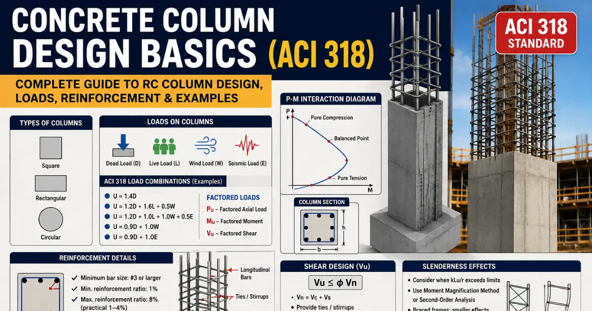
Concrete columns are one of the most important structural elements in any building. They are vertical load-bearing members designed to transfer loads safely from the slabs, beams, and roofs down to the foundation. A properly designed column primarily resists axial compression, but it can also withstand bending moments, shear forces, and in some cases torsional loads caused by wind, earthquakes, or uneven loading. Without strong and properly designed columns, a building cannot maintain its structural integrity or safely support its intended loads. Concrete Calculator
In residential, commercial, and industrial construction, concrete columns play a critical role in ensuring safety, stability, and durability. They provide the main load path for the structure, preventing excessive settlement, cracking, or structural failure. Well-designed columns improve a building’s ability to resist gravity loads, lateral forces, and long-term environmental effects, making them one of the most essential components of reinforced concrete construction.
Concrete columns come in several types depending on their geometry, reinforcement details, and structural behavior. The most common classifications include:
- Short Columns – Designed with a low slenderness ratio and primarily fail due to concrete crushing under compression.
- Slender Columns – Taller columns that are susceptible to buckling and require additional stability considerations during design.
- Tied Columns – Reinforced with longitudinal bars enclosed by closed ties (hoops). These are the most commonly used columns in residential and commercial buildings throughout the United States.
- Spiral Columns – Contain continuous spiral reinforcement that provides improved confinement, ductility, and seismic performance compared to tied columns.
- Rectangular Columns – Widely used in buildings because they integrate easily with walls and beams.
- Square Columns – Popular for residential structures due to their simple layout and balanced load distribution.
- Circular Columns – Commonly used in bridges, parking garages, industrial facilities, and architectural applications where aesthetics or uniform load distribution is important.
Modern concrete column design in the United States follows the Strength Design approach, also known as Load and Resistance Factor Design (LRFD). Under this philosophy, engineers apply load factors to expected loads and reduce the nominal strength of structural members using strength reduction factors. This ensures that every column has an adequate safety margin against failure while remaining economical and efficient. The LRFD method accounts for uncertainties in material properties, construction quality, and loading conditions, making it the preferred design methodology for reinforced concrete structures.
The primary design standard for reinforced concrete columns in the United States is ACI 318 (Building Code Requirements for Structural Concrete). Developed and continuously updated by the American Concrete Institute, ACI 318 has evolved over decades through extensive research, laboratory testing, field performance, and lessons learned from real-world structures. Today, it serves as the foundation for concrete design across the U.S., providing engineers with comprehensive requirements for column sizing, reinforcement detailing, strength calculations, durability, serviceability, and seismic design. Its widespread adoption ensures consistent, reliable, and safe structural design practices across residential, commercial, and infrastructure projects.
Classification of Concrete Columns (ACI 318)
The American Concrete Institute ACI 318 code classifies reinforced concrete columns based on their slenderness, structural behavior, and reinforcement detailing. Understanding these classifications is essential because each type has different design requirements, load-carrying behavior, and stability considerations.
1. Short Columns vs. Slender Columns
One of the most important classifications in ACI 318 is whether a column behaves as a short column or a slender column.
Short Columns
A short column has a relatively small unsupported height compared to its cross-sectional dimensions. These columns primarily resist axial compression and bending moments, with minimal risk of buckling.
Characteristics include:
- Higher load-carrying capacity
- Buckling effects are generally insignificant
- Simpler design calculations
- Most common in low-rise residential and commercial buildings
When a column satisfies the ACI 318 slenderness limits, slenderness effects may be ignored, allowing engineers to use standard strength calculations without additional moment magnification.
Slender Columns
A slender column has a larger unsupported height relative to its cross-sectional size. Because of its geometry, it experiences additional bending due to buckling (second-order or P-Δ effects).
Characteristics include:
- Lower stability than short columns
- Additional bending moments caused by axial loads
- Requires moment magnification or second-order analysis
- Common in multi-story buildings and tall structures
Slenderness Ratio (kℓu/r)
ACI 318 evaluates column slenderness using the slenderness ratio:
kℓu/r
Where:
- k = Effective length factor
- ℓu = Unsupported column length
- r = Radius of gyration of the column section
A larger kℓu/r value indicates a greater likelihood of buckling. If the calculated slenderness ratio remains within the ACI 318 limits, engineers can generally ignore slenderness effects. If the limits are exceeded, additional design procedures such as moment magnification or second-order analysis must be applied.
2. Braced vs. Unbraced Frames
ACI 318 also distinguishes columns based on the structural frame that supports them.
Braced Frames (Non-Sway Frames)
In a braced frame, lateral movement is restrained by structural elements such as:
- Shear walls
- Braced frames
- Concrete cores
Characteristics:
- Minimal lateral sway
- Lower secondary moments
- Higher overall stability
- Simpler column design
Because lateral displacement is limited, columns in braced frames generally experience smaller additional bending moments.
Unbraced Frames (Sway Frames)
An unbraced frame allows noticeable lateral movement under wind or seismic loading.
Characteristics:
- Larger lateral displacement
- Greater second-order (P-Δ) effects
- Increased bending moments
- Requires more detailed stability analysis
Columns in sway frames must be designed carefully because lateral drift significantly influences their strength and serviceability.
3. Tied Columns vs. Spirally Reinforced Columns
ACI 318 classifies reinforced concrete columns according to their transverse reinforcement.
Tied Columns
A tied column contains longitudinal reinforcing bars enclosed by closed ties (hoops) placed at specified spacing.
Features include:
- Most commonly used column type in the United States
- Simple and economical construction
- Suitable for residential, commercial, and industrial buildings
- Provides adequate confinement for normal structural applications
Advantages:
- Easy reinforcement placement
- Lower construction cost
- Widely accepted for standard building projects
Spirally Reinforced Columns
A spirally reinforced column uses continuous spiral reinforcement wrapped around the longitudinal bars.
Features include:
- Continuous confinement of the concrete core
- Improved ductility
- Better energy absorption during earthquakes
- Higher deformation capacity before failure
Advantages:
- Superior confinement of concrete
- Greater resistance to sudden brittle failure
- Enhanced performance in seismic regions
- Better post-yield behavior under heavy loading
Because spiral reinforcement provides more effective confinement than conventional ties, spirally reinforced columns generally offer better ductility and seismic performance, making them a preferred choice for bridges, high-rise buildings, and structures located in earthquake-prone areas.
Quick Comparison Table
| Classification | Description | Typical Application |
|---|---|---|
| Short Column | Low slenderness ratio, buckling effects usually negligible | Low- and mid-rise buildings |
| Slender Column | High slenderness ratio, buckling must be considered | High-rise buildings and tall structures |
| Braced Frame | Lateral movement restrained by shear walls or bracing | Buildings with shear walls or concrete cores |
| Unbraced Frame | Frame allowed to sway under lateral loads | Moment-resisting frame systems |
| Tied Column | Longitudinal bars enclosed with closed ties | Most residential and commercial buildings |
| Spirally Reinforced Column | Continuous spiral reinforcement around longitudinal bars | Bridges, seismic structures, and heavy-load applications |
Materials Used in Concrete Column Design
The strength, durability, and long-term performance of a reinforced concrete column depend largely on the quality of its materials. According to American Concrete Institute ACI 318, engineers must select concrete and reinforcing steel that satisfy both structural strength and durability requirements. Proper material selection helps columns safely resist compression, bending, shear, and environmental exposure throughout the structure’s service life.
1. Concrete Compressive Strength (f’c)
The most important property of structural concrete is its specified compressive strength, denoted as f’c (pronounced “f-prime-c”). This value is typically measured at 28 days after casting and is expressed in pounds per square inch (psi) in the United States.
Higher compressive strength generally increases the load-carrying capacity of a column, although it may also affect stiffness, shrinkage, and cost.
Typical Concrete Strengths
| Concrete Strength (f’c) | Common Applications |
|---|---|
| 3,000 psi | Light residential construction |
| 4,000 psi | Standard residential foundations and columns |
| 5,000 psi | Commercial buildings and heavily loaded columns |
| 6,000 psi | Multi-story buildings and parking structures |
| 8,000 psi and above | High-rise buildings, bridges, and special structures |
For most residential and commercial buildings in the U.S., 4,000 psi and 5,000 psi concrete are the most commonly specified strengths.
2. Reinforcing Steel Yield Strength (fy)
Concrete performs exceptionally well in compression but is relatively weak in tension. To resist tensile stresses and improve ductility, reinforced concrete columns contain steel reinforcing bars (rebar).
The strength of reinforcing steel is measured by its yield strength (fy).
Common Reinforcing Steel Grades
| Steel Grade | Yield Strength |
|---|---|
| Grade 40 | 40 ksi (40,000 psi) |
| Grade 60 | 60 ksi (60,000 psi) |
| Grade 80 | 80 ksi (used in specialized projects) |
Grade 60 (60 ksi) reinforcing steel is the standard choice for most reinforced concrete buildings in the United States because it provides an excellent balance of strength, ductility, availability, and cost.
Steel reinforcement in columns consists of:
- Longitudinal reinforcing bars
- Ties (hoops) or spiral reinforcement
- Properly anchored lap splices and development lengths
3. Modulus of Elasticity and Stress-Strain Behavior
Modulus of Elasticity (Ec)
The modulus of elasticity represents the stiffness of concrete and indicates how much it deforms under load.
Important characteristics include:
- Higher-strength concrete generally has a higher modulus of elasticity.
- Stiffer concrete experiences less elastic deformation under service loads.
- The modulus of elasticity is used when calculating column deflection, stiffness, and second-order effects.
Stress-Strain Behavior of Concrete
Concrete exhibits a nonlinear stress-strain relationship.
Key characteristics:
- Initially behaves almost linearly under small loads.
- Reaches maximum compressive stress at approximately 0.003 compressive strain, which is commonly used in ACI 318 design.
- After reaching peak strength, concrete gradually loses its load-carrying capacity as crushing begins.
Stress-Strain Behavior of Reinforcing Steel
Reinforcing steel behaves differently from concrete.
Its behavior includes:
- Linear elastic response up to the yield point.
- Yielding occurs at the specified fy value.
- After yielding, steel undergoes significant plastic deformation before fracture.
This ductile behavior allows reinforced concrete columns to provide warning before failure and improves structural safety during extreme loading events.
4. Durability Requirements
In addition to strength, ACI 318 places significant emphasis on durability so that concrete columns can maintain their performance throughout their intended service life.
Concrete Cover
Concrete cover is the minimum thickness of concrete placed between the reinforcing steel and the exposed surface.
Adequate cover provides:
- Protection against corrosion of reinforcement
- Improved fire resistance
- Better bond between concrete and steel
- Increased durability in harsh environments
Required cover depends on factors such as:
- Indoor or outdoor exposure
- Contact with soil
- Weather conditions
- Marine or coastal environments
- Exposure to deicing chemicals
Exposure Classes
ACI 318 defines exposure classes to ensure concrete mixtures and detailing are appropriate for environmental conditions.
Common exposure categories include:
| Exposure Class | Primary Concern |
|---|---|
| F | Freeze-thaw cycles |
| S | Sulfate exposure |
| W | Water exposure and permeability |
| C | Corrosion caused by chlorides (such as deicing salts or seawater) |
Each exposure class may require adjustments to:
- Minimum concrete strength
- Water-cement ratio
- Air entrainment
- Cementitious materials
- Concrete cover thickness
Meeting these durability requirements helps minimize cracking, corrosion, and deterioration, allowing reinforced concrete columns to perform safely for decades with reduced maintenance.
Loads and Load Combinations
Concrete columns are designed to safely resist all loads that may act on a structure during its service life. According to American Concrete Institute ACI 318, the design of reinforced concrete columns follows the Strength Design (Load and Resistance Factor Design – LRFD) approach. In this method, actual loads are multiplied by load factors to account for uncertainties, ensuring that the column has sufficient strength and an appropriate margin of safety.
Types of Structural Loads
1. Dead Load (D)
Dead load (D) is the permanent weight of all structural and fixed non-structural components of a building. These loads remain relatively constant throughout the life of the structure.
Typical dead loads include:
- Concrete slabs
- Beams and columns
- Walls and partitions
- Roofing materials
- Floor finishes
- Mechanical and electrical equipment permanently attached to the building
Dead load is generally the largest sustained load acting on a concrete column.
2. Live Load (L)
Live load (L) consists of movable or temporary loads that vary over time depending on how the building is used.
Examples include:
- Occupants
- Furniture
- Office equipment
- Storage materials
- Movable machinery
Unlike dead loads, live loads are not always present at their maximum value, but they must still be considered in structural design to ensure adequate safety.
3. Wind Load (W)
Wind load (W) acts laterally on a structure and can produce significant bending moments in columns, especially in taller buildings.
Wind loads depend on factors such as:
- Building height
- Geographic wind speed
- Terrain and surrounding structures
- Building shape
- Exposure category
Wind loading can increase axial forces while also generating additional bending moments that must be included in column design.
4. Seismic Load (E)
Seismic load (E) represents earthquake forces acting on a structure.
During an earthquake, columns experience:
- Lateral forces
- Dynamic loading
- Reversed bending moments
- Increased shear forces
- Additional axial load variations
Structures located in seismic regions require special detailing to improve ductility and energy dissipation, allowing columns to perform safely during earthquake events.
5. Other Possible Loads
Depending on the project, engineers may also consider additional loads, including:
- Snow loads
- Rain loads
- Soil and earth pressure
- Hydrostatic pressure
- Impact loads
- Construction loads
- Temperature and shrinkage effects
Although not every project includes these loads, they may govern the design in certain structures or environmental conditions.zz
ACI Load Combinations
ACI 318 uses factored load combinations to evaluate the most critical loading scenarios a column may experience. These combinations increase the applied loads using prescribed load factors to account for uncertainties in loading conditions and material behavior.
Some common LRFD load combinations include:
- U = 1.4D
- U = 1.2D + 1.6L + 0.5(Lr or S or R)
- U = 1.2D + 1.0W + L + 0.5(Lr or S or R)
- U = 1.2D + 1.0E + L
- U = 0.9D + 1.0W
- U = 0.9D + 1.0E
Where:
- U = Required factored load
- D = Dead load
- L = Live load
- W = Wind load
- E = Earthquake (seismic) load
- Lr = Roof live load
- S = Snow load
- R = Rain load
The governing load combination is the one that produces the highest demand on the column and is used for final design.
Factored Design Forces
After applying the required load combinations, engineers calculate the factored design forces used to verify the strength of the column.
Factored Axial Load (Pu)
Pu is the factored axial compressive load acting on the column after applying the appropriate load combinations.
It is used to:
- Determine the required column size
- Calculate longitudinal reinforcement
- Evaluate compression capacity
Factored Bending Moment (Mu)
Mu is the factored bending moment resulting from eccentric loading, wind, earthquakes, or frame action.
It is used to:
- Check flexural strength
- Design reinforcement layout
- Develop axial load–moment (P–M) interaction diagrams
Factored Shear Force (Vu)
Vu is the factored shear force acting on the column.
Although columns are primarily compression members, they must also resist shear caused by:
- Lateral loads
- Beam reactions
- Earthquakes
- Wind forces
The shear capacity of the column is verified by considering both the concrete contribution and the transverse reinforcement (ties or spiral reinforcement).
Summary Table
| Symbol | Description | Typical Purpose |
|---|---|---|
| D | Dead Load | Permanent structural weight |
| L | Live Load | Occupancy and movable loads |
| W | Wind Load | Lateral wind effects |
| E | Seismic Load | Earthquake forces |
| U | Factored Load Combination | LRFD design load |
| Pu | Factored Axial Load | Compression design |
| Mu | Factored Bending Moment | Flexural design |
| Vu | Factored Shear Force | Shear design |
By evaluating all applicable loads and applying the required ACI 318 load combinations, engineers can design reinforced concrete columns that safely resist both everyday service conditions and extreme loading events while maintaining structural reliability and code compliance.
Preliminary Sizing and Design Steps
Before performing detailed structural calculations, engineers establish the preliminary size of a concrete column. This initial sizing ensures that the column has sufficient strength, stiffness, and space for reinforcement while meeting the requirements of American Concrete Institute ACI 318. After selecting a preliminary section, the column is verified through detailed strength, stability, and serviceability checks.
1. Select Minimum Column Dimensions
The first step is choosing an appropriate column size based on the building type, loading conditions, architectural constraints, and applicable code requirements.
For cast-in-place reinforced concrete buildings, a minimum column dimension of approximately 12 inches (305 mm) is commonly used in practice. Larger buildings or heavily loaded columns generally require larger cross-sections.
Typical preliminary sizes include:
| Column Size | Common Applications |
|---|---|
| 12″ × 12″ | Light residential construction |
| 12″ × 16″ | Small commercial buildings |
| 16″ × 16″ | Multi-story buildings |
| 18″ × 18″ or larger | High-load columns and taller structures |
The selected dimensions should also provide adequate space for reinforcing bars, concrete placement, and proper concrete consolidation.
2. Calculate Gross Cross-Sectional Area (Ag)
The gross cross-sectional area (Ag) is the total area of the concrete section before subtracting the reinforcing steel.
For rectangular columns:
Ag = Width × Depth
Example:
- Column size = 16 in × 16 in
- Ag = 16 × 16 = 256 in²
The gross area is used in many ACI 318 design calculations, including:
- Axial load capacity
- Reinforcement ratio
- Strength checks
- Interaction diagram development
3. Select Reinforcement Ratio (ρ)
After determining the column dimensions, engineers estimate the amount of longitudinal reinforcement required.
The reinforcement ratio (ρ) is defined as:
ρ = Ast / Ag
Where:
- ρ = Reinforcement ratio
- Ast = Total area of longitudinal reinforcing steel
- Ag = Gross cross-sectional area
ACI 318 Reinforcement Limits
| Requirement | Reinforcement Ratio |
|---|---|
| Minimum | 1% |
| Maximum (Code Limit) | 8% |
| Practical Design Range | 1%–4% |
Using reinforcement within the 1% to 4% practical range offers several advantages:
- Easier concrete placement
- Better consolidation around reinforcing bars
- Improved constructability
- Reduced reinforcement congestion
- More economical construction
Although ACI 318 permits reinforcement ratios up to 8%, such high percentages are rarely used because they make concrete placement and vibration much more difficult.
4. Provide Adequate Clear Cover
Clear cover is the minimum distance between the outer surface of the concrete and the nearest reinforcing steel.
Proper concrete cover is essential for:
- Corrosion protection
- Fire resistance
- Long-term durability
- Proper bond between concrete and reinforcement
For interior cast-in-place columns, a typical clear cover of 1.5 inches (38 mm) is commonly provided.
Greater cover may be required for columns exposed to:
- Outdoor weather
- Soil contact
- Marine environments
- Deicing salts
- Severe environmental conditions
- Fire-resistance requirements
Increasing concrete cover improves durability but should be balanced with structural detailing and reinforcement placement requirements.
Typical Preliminary Design Workflow
Engineers generally follow these basic steps during preliminary column sizing:
- Determine the factored loads acting on the column.
- Select an initial column size based on expected loading and architectural constraints.
- Calculate the gross cross-sectional area (Ag).
- Estimate the required longitudinal reinforcement while maintaining a reinforcement ratio between 1% and 4% (within the ACI 318 limits of 1% to 8%).
- Provide the required clear cover and arrange reinforcing bars with adequate spacing.
- Perform detailed strength, slenderness, interaction, and serviceability checks to confirm the final design.
Quick Reference Table
| Design Parameter | Typical Recommendation |
|---|---|
| Minimum Cast-in-Place Column Dimension | 12 in (305 mm) |
| Gross Area (Ag) | Width × Depth |
| Minimum Reinforcement Ratio (ρ) | 1% |
| Maximum Reinforcement Ratio (ACI 318) | 8% |
| Practical Reinforcement Ratio | 1%–4% |
| Typical Interior Clear Cover | 1.5 in (38 mm) |
| Exterior/Exposed Columns | Increased cover based on exposure conditions |
Establishing appropriate preliminary dimensions, reinforcement ratios, and concrete cover provides a solid foundation for detailed structural design. These initial decisions help ensure that reinforced concrete columns are strong, durable, constructible, and compliant with ACI 318 requirements while minimizing unnecessary material costs.
Axial Load Capacity (Pure Compression)
The primary function of a reinforced concrete column is to resist axial compression while safely transferring loads from the structure above to the foundation. In many practical situations, columns are also subjected to bending moments and shear forces. However, understanding the pure compression capacity is the first step in reinforced concrete column design. According to American Concrete Institute ACI 318, the axial strength of a short column depends on the strength of both the concrete and the reinforcing steel.
Nominal Axial Strength (Pn)
The nominal axial strength (Pn) represents the theoretical compression capacity of a reinforced concrete column before applying any strength reduction factors.
For a concentrically loaded reinforced concrete column:
Pn=0.85fc′(Ag−Ast)+fyAst
Where:
- Pn = Nominal axial strength
- f’c = Specified concrete compressive strength
- Ag = Gross cross-sectional area
- Ast = Total area of longitudinal reinforcement
- fy = Yield strength of reinforcing steel
The first term represents the load carried by the concrete, while the second term represents the contribution of the reinforcing steel.
Strength Reduction Factors (φ)
ACI 318 uses strength reduction factors (φ) to account for uncertainties in materials, construction quality, and loading conditions.
Tied Columns
For columns reinforced with closed ties:
- φ = 0.65
Design strength:
ϕPn=0.65Pn
Spirally Reinforced Columns
For columns with continuous spiral reinforcement:
- φ = 0.75
Design strength:
ϕPn=0.75Pn
Because spiral reinforcement provides better confinement of the concrete core, spirally reinforced columns receive a higher strength reduction factor than tied columns.
Maximum Axial Load Limits
ACI 318 limits the usable axial design strength for concentrically loaded columns to provide an additional safety margin and account for unavoidable construction imperfections and load eccentricities.
Tied Columns
Maximum usable axial load:
Pu≤0.80ϕPn,max
This means the factored axial load should not exceed 80% of the design axial strength.
Spirally Reinforced Columns
Maximum usable axial load:
Pu≤0.85ϕPn,max
Because spiral reinforcement improves confinement and ductility, ACI 318 permits 85% of the design axial strength to be used.
Comparison of Design Factors
| Column Type | Strength Reduction Factor (φ) | Maximum Usable Axial Strength |
|---|---|---|
| Tied Column | 0.65 | 0.80φPn,max |
| Spiral Column | 0.75 | 0.85φPn,max |
Example Calculation
Consider a short tied reinforced concrete column with the following properties:
- Concrete strength, f’c = 4,000 psi
- Steel yield strength, fy = 60,000 psi
- Column size = 16 in × 16 in
- Gross area, Ag = 256 in²
- Total reinforcement area, Ast = 4.00 in²
Step 1: Calculate Nominal Axial Strength
Concrete contribution:
0.85×4000×(256−4)=856,800 lb
Steel contribution:
60,000×4=240,000 lb
Nominal axial strength:
Pn=856,800+240,000=1,096,800 lb
Pn≈1,097 kips
Step 2: Apply Strength Reduction Factor
For a tied column:
ϕPn=0.65×1,096,800=712,920 lb
ϕPn≈713 kips
Step 3: Determine Maximum Permitted Axial Load
ACI 318 limits the usable strength for tied columns to:
0.80×713=570 kips
Therefore, the maximum factored axial load permitted for this example is approximately:
Pu≈570 kips
Important Design Notes
- The equations above apply primarily to short columns under concentric (pure axial) compression.
- Real building columns almost always experience some load eccentricity, producing combined axial compression and bending.
- Slender columns require additional checks for second-order (P–Δ) effects.
- Final design should also verify reinforcement detailing, clear cover, confinement, shear capacity, and load combinations in accordance with ACI 318.
Understanding the nominal axial strength (Pn) and the applicable strength reduction factors (φ) provides the foundation for reinforced concrete column design. These calculations help engineers ensure that columns can safely resist factored loads while maintaining the required safety margins and structural reliability.
Combined Axial Load + Bending (Most Common Design Case)
In real-world buildings, reinforced concrete columns rarely experience pure axial compression. Most columns are subjected to a combination of axial load (Pu) and bending moment (Mu) due to beam reactions, eccentric loading, wind, earthquakes, and frame action. This condition is known as combined axial load and bending, and it is the most common design scenario addressed by American Concrete Institute ACI 318.
Because both compression and bending act simultaneously, engineers must verify that the column has sufficient capacity to resist the combined effects rather than checking each force independently.
Interaction Diagram (P-M Diagram)
The primary design tool for evaluating combined loading is the Axial Load–Moment Interaction Diagram (P-M Diagram).
A P-M diagram illustrates the relationship between:
- Axial Load (P)
- Bending Moment (M)
Each point on the interaction curve represents a safe combination of axial load and bending moment that the column can resist.
General interpretation:
- Points inside the curve → Safe design
- Points on the curve → Maximum design capacity
- Points outside the curve → Unsafe (column must be redesigned)
The P-M interaction diagram is one of the most important tools used in reinforced concrete column design because it accounts for the combined behavior of concrete and reinforcing steel under different loading conditions.
Control Points on the Interaction Curve
Several important points define the shape of the interaction diagram.
1. Pure Compression
At the top of the interaction curve:
- Maximum axial load
- Negligible bending moment
- Entire cross-section is in compression
This condition represents the theoretical maximum compression capacity of the column.
2. Balanced Point
The balanced point occurs when:
- Concrete reaches its ultimate compressive strain.
- Tensile reinforcement reaches its yield strength at the same time.
This point separates two different failure modes:
- Compression-controlled behavior
- Tension-controlled behavior
It is one of the most significant locations on the interaction diagram because it marks the transition between brittle and ductile structural behavior.
3. Pure Tension
At the opposite end of the interaction curve:
- Axial compression becomes zero.
- Reinforcing steel carries nearly all the applied force.
- Concrete contributes very little because it has low tensile strength.
Although pure tension is uncommon in typical building columns, it is included to define the complete interaction relationship.
Load Eccentricity
Combined loading occurs because the applied load is rarely perfectly centered on the column.
The eccentricity (e) is calculated as:
e=Pu/Mu
Where:
- e = Load eccentricity
- Mu = Factored bending moment
- Pu = Factored axial load
A larger eccentricity produces:
- Greater bending stresses
- Lower axial load capacity
- Increased reinforcement demand
Even small construction tolerances or beam framing can introduce eccentricity, which is why ACI 318 generally assumes that practical columns experience some degree of bending.
Strain Compatibility Method
ACI 318 evaluates column strength using the strain compatibility method.
This method assumes:
- Plane sections remain plane after bending.
- Concrete and reinforcing steel deform together.
- Strain varies linearly across the cross-section.
Using the strain distribution, engineers calculate:
- Concrete compression force
- Steel compression force
- Steel tension force
The internal forces are then balanced to determine the column’s axial and moment capacities.
The strain compatibility method forms the basis for generating accurate P-M interaction diagrams.
Whitney Stress Block
To simplify compression calculations, ACI 318 uses the Whitney Rectangular Stress Block.
Its main assumptions are:
- Concrete compression stress is represented by a uniform rectangular block.
- Average compressive stress equals 0.85f’c.
- The equivalent compression block depth is determined using ACI 318 parameters.
The concrete compression force is expressed as:
C=0.85fc′×b×a
Where:
- C = Concrete compression force
- 0.85f’c = Equivalent concrete stress
- b = Width of compression zone
- a = Depth of the equivalent rectangular stress block
The Whitney stress block greatly simplifies hand calculations while providing results that closely match the actual nonlinear behavior of reinforced concrete.
Uniaxial vs. Biaxial Bending
Columns may bend about one axis or two axes simultaneously.
Uniaxial Bending
Uniaxial bending occurs when the bending moment acts about only one principal axis.
Characteristics include:
- Simpler analysis
- Standard P-M interaction diagram is generally sufficient
- Common in beams framing into one direction
Examples:
- Rectangular columns subjected to bending only about the strong axis
- Wall-supported columns with one primary bending direction
Biaxial Bending
Biaxial bending occurs when moments act simultaneously about both principal axes.
Characteristics include:
- More complex stress distribution
- Reduced load-carrying capacity
- Requires biaxial interaction analysis or specialized design software
- Common in corner columns and columns subjected to wind or seismic forces from multiple directions
Because columns in modern buildings often experience multidirectional loading, biaxial bending is frequently considered during final structural design.
Summary Table
| Design Concept | Description |
|---|---|
| P-M Interaction Diagram | Primary tool for evaluating combined axial load and bending capacity |
| Pure Compression Point | Maximum axial capacity with little or no bending |
| Balanced Point | Concrete reaches ultimate compression while tensile steel yields simultaneously |
| Pure Tension Point | Reinforcing steel resists nearly all applied force |
| Eccentricity (e = Mu/Pu) | Measures how far the load acts from the column’s centroid |
| Strain Compatibility Method | Calculates internal forces based on linear strain distribution |
| Whitney Stress Block | Uses a rectangular compression block with 0.85f’c to simplify concrete compression analysis |
| Uniaxial Bending | Bending about one principal axis |
| Biaxial Bending | Simultaneous bending about both principal axes requiring more advanced analysis |
By combining axial load, bending moments, strain compatibility, and the P-M interaction diagram, engineers can accurately determine whether a reinforced concrete column satisfies ACI 318 strength requirements. This comprehensive approach ensures that columns remain safe, stable, and capable of supporting complex loading conditions encountered in modern buildings.
Shear Design in Columns
Although reinforced concrete columns are primarily designed to resist axial compression and bending moments, they must also have adequate capacity to resist shear forces. Shear forces commonly develop due to wind loads, earthquake forces, beam reactions, frame action, and unbalanced loading. If shear is not properly addressed, a column can experience a sudden and brittle failure. Therefore, American Concrete Institute ACI 318 requires every reinforced concrete column to be checked for shear strength and provided with sufficient transverse reinforcement.
Factored Shear Force (Vu)
The first step in shear design is determining the factored shear force (Vu) obtained from the governing load combinations.
Where:
- Vu = Factored shear force acting on the column
The design requirement is:
Vu≤ϕVn
Where:
- Vu = Factored shear demand
- Vn = Nominal shear strength of the column
- φ = Strength reduction factor for shear (as specified by ACI 318)
The nominal shear strength consists of:
- Concrete contribution (Vc)
- Shear reinforcement contribution (Vs)
Therefore:
Vn=Vc+Vs
If the applied shear force exceeds the concrete’s shear capacity alone, additional transverse reinforcement must be provided.
Shear Reinforcement (Stirrups or Ties)
Concrete columns use transverse reinforcement, commonly called ties (or stirrups in some applications), to resist shear and improve overall structural performance.
The primary functions of shear reinforcement are:
- Resist shear forces
- Hold longitudinal reinforcing bars in their proper position
- Confine the concrete core
- Prevent buckling of longitudinal reinforcement under compression
- Improve ductility, particularly during seismic events
Tied Columns
In tied columns, closed steel ties are placed around the longitudinal reinforcing bars at regular intervals.
Advantages include:
- Increased shear resistance
- Better confinement of concrete
- Improved structural stability
- Easier reinforcement placement during construction
Spiral Columns
Instead of individual ties, spiral columns use a continuous spiral reinforcement wrapped around the longitudinal bars.
Compared with tied columns, spiral reinforcement provides:
- Better confinement of the concrete core
- Improved ductility
- Higher energy absorption
- Superior performance during earthquakes and cyclic loading
Spacing Requirements for Ties
ACI 318 specifies maximum spacing limits for transverse reinforcement to ensure adequate confinement and shear resistance.
The spacing of ties should not exceed the smallest of the following:
- 16 times the diameter of the smallest longitudinal reinforcing bar
- 48 times the diameter of the tie (transverse reinforcement) bar
- The least dimension of the column cross-section
These limits help ensure that:
- Longitudinal bars remain laterally supported.
- Concrete is effectively confined.
- Shear cracks are controlled.
- Compression reinforcement does not buckle.
In regions of high seismic activity or near beam-column joints, ACI 318 often requires closer tie spacing to enhance confinement and improve the column’s ductile behavior under cyclic loading.
Typical Shear Design Procedure
Engineers generally follow these steps when designing column shear reinforcement:
- Calculate the factored shear force (Vu) from the governing load combinations.
- Determine the nominal shear strength (Vn = Vc + Vs).
- Verify that Vu ≤ φVn.
- Design the required transverse reinforcement if additional shear capacity is needed.
- Check that tie spacing complies with ACI 318 maximum spacing requirements.
- Confirm proper detailing, including tie anchorage, corner bar restraint, and seismic confinement where applicable.
Summary Table
| Design Parameter | Description |
|---|---|
| Vu | Factored shear force acting on the column |
| Design Check | Vu ≤ φVn |
| Nominal Shear Strength (Vn) | Vc + Vs (concrete contribution + reinforcement contribution) |
| Shear Reinforcement | Closed ties (stirrups) or continuous spiral reinforcement |
| Functions of Ties | Resist shear, confine concrete, support longitudinal bars, prevent bar buckling |
| Maximum Tie Spacing | Lesser of 16db (longitudinal bar), 48db (tie bar), or least column dimension |
| Seismic Regions | Closer tie spacing is typically required for improved confinement and ductility |
Proper shear design is essential for the safe performance of reinforced concrete columns. By checking Vu, providing adequate transverse reinforcement, and complying with ACI 318 tie spacing requirements, engineers can ensure that columns remain stable, ductile, and capable of resisting both everyday service loads and extreme events such as strong winds and earthquakes.
Detailing Requirements (Critical for USA Practice)
Proper detailing is just as important as strength calculations in reinforced concrete column design. Even if a column has adequate theoretical capacity, poor reinforcement detailing can significantly reduce its performance during heavy loading, wind, or earthquakes. For this reason, American Concrete Institute ACI 318 provides comprehensive detailing requirements covering reinforcement placement, tie spacing, lap splices, development length, and seismic reinforcement. Correct detailing ensures that columns remain strong, ductile, durable, and constructible throughout their service life.
Longitudinal Reinforcement Arrangement
Longitudinal reinforcement consists of the vertical reinforcing bars that carry axial compression and bending forces.
General ACI 318 detailing guidelines include:
- Reinforcing bars should be distributed as uniformly as possible around the perimeter of the column.
- Bars should be positioned symmetrically to improve strength under bending from different directions.
- Corner bars must be enclosed and restrained by ties or spiral reinforcement.
- Interior bars should also be adequately supported by transverse reinforcement.
Minimum Bar Size
For reinforced concrete columns, the longitudinal reinforcement should generally consist of No. 3 (#3) bars or larger, although No. 5 (#5), No. 6 (#6), and No. 8 (#8) bars are far more common in structural columns due to their greater strength and practical constructability.
Typical minimum number of longitudinal bars:
| Column Shape | Minimum Longitudinal Bars |
|---|---|
| Rectangular or Square | 4 bars |
| Circular (Tied) | 6 bars |
| Spiral Columns | 6 bars or more |
Tie (Stirrup) Size and Spacing
Transverse reinforcement, commonly called ties or stirrups, serves several important functions:
- Resists shear forces
- Confines the concrete core
- Prevents buckling of longitudinal bars
- Maintains reinforcement alignment during concrete placement
Tie Size
ACI 318 generally requires ties to be No. 3 (#3) bars or larger. Larger tie sizes may be necessary for heavily reinforced columns or larger longitudinal reinforcement.
Maximum Tie Spacing
The vertical spacing of ties should not exceed the smallest of the following limits:
- 16 × db (diameter of the smallest longitudinal reinforcing bar)
- 48 × db (diameter of the tie bar)
- Least dimension of the column cross-section
In addition, many designers use the practical guideline of keeping tie spacing no greater than approximately one-quarter of the least column dimension in critical regions to improve confinement, particularly where higher ductility is desired.
Closer tie spacing provides:
- Better confinement
- Improved shear resistance
- Increased ductility
- Greater earthquake performance
Lap Splices
When reinforcing bars cannot be supplied in a single continuous length, they must be connected using lap splices or mechanical couplers.
ACI 318 requires lap splice lengths based on:
- Concrete strength (f’c)
- Steel yield strength (fy)
- Bar diameter
- Concrete cover
- Bar spacing
- Reinforcement location
Good detailing practices include:
- Locate lap splices away from regions of maximum stress whenever possible.
- Avoid splicing all bars at the same location unless specifically permitted.
- Stagger lap splices to reduce reinforcement congestion and improve load transfer.
- Ensure ties continue through splice regions to provide proper confinement.
Development Length
The development length (Ld) is the minimum embedment length required for a reinforcing bar to fully develop its yield strength through bond with the surrounding concrete.
Development length depends on factors such as:
- Bar size
- Concrete compressive strength
- Steel yield strength
- Concrete cover
- Bar coating (epoxy-coated or uncoated)
- Confinement provided by transverse reinforcement
Providing adequate development length ensures:
- Efficient force transfer between steel and concrete
- Prevention of bond failure
- Reliable structural performance under design loads
Seismic Detailing (ACI 318 Chapter 18)
For structures located in earthquake-prone regions, ACI 318 Chapter 18 introduces additional detailing requirements to improve ductility and energy dissipation.
Typical seismic detailing provisions include:
- Reduced tie spacing in plastic hinge regions
- Continuous confinement reinforcement near beam-column joints
- 135° seismic hooks on transverse reinforcement
- Increased confinement at column ends
- Proper anchorage of longitudinal bars
- Strong-column/weak-beam design philosophy
- Enhanced detailing to prevent brittle failure during cyclic loading
These requirements enable reinforced concrete columns to withstand repeated inelastic deformation while maintaining structural integrity during major earthquakes.
Bar Placement and Bundling
Correct placement of reinforcing bars is essential for both structural performance and concrete quality.
Bar Placement
ACI 318 requires that reinforcement be placed so that:
- Adequate concrete cover is maintained.
- Bars have sufficient clear spacing for concrete flow and consolidation.
- Reinforcement does not interfere with proper vibration during placement.
- Congestion is minimized to reduce honeycombing and voids.
Proper bar placement improves bond, durability, and overall constructability.
Bundling Limits
In heavily loaded columns, reinforcing bars may sometimes be grouped into bundles.
Important considerations include:
- Bundled bars should comply with ACI 318 detailing provisions.
- Bundles should not create excessive reinforcement congestion.
- Additional confinement may be required around bundled reinforcement.
- Proper concrete consolidation around bundled bars must be ensured.
- Mechanical couplers may be preferred over excessive bundling in heavily reinforced columns.
Although bundling can simplify reinforcement placement in large columns, excessive bundling may reduce concrete quality and make construction more difficult.
Summary Table
| Detailing Requirement | Typical ACI 318 Practice |
|---|---|
| Minimum Longitudinal Bar Size | #3 bar or larger (larger bars commonly used in practice) |
| Minimum Number of Bars | 4 (rectangular/square), 6 (circular or spiral columns) |
| Tie Size | #3 bar or larger |
| Maximum Tie Spacing | Lesser of 16db (longitudinal bar), 48db (tie bar), or least column dimension |
| Practical Critical-Region Spacing | Often limited to about ¼ of the least column dimension for improved confinement where appropriate |
| Lap Splices | Designed according to ACI 318 development and splice requirements |
| Development Length (Ld) | Based on bar size, concrete strength, steel strength, cover, and confinement |
| Seismic Detailing | Follow ACI 318 Chapter 18 with closer ties, 135° hooks, and enhanced confinement |
| Bar Placement | Maintain proper cover, spacing, and concrete consolidation |
| Bar Bundling | Permitted within ACI 318 limits while avoiding excessive congestion |
Proper detailing is one of the most critical aspects of reinforced concrete column design in the United States. By following ACI 318 requirements for longitudinal reinforcement, transverse ties, lap splices, development length, seismic detailing, and bar placement, engineers ensure that concrete columns achieve not only their calculated strength but also the ductility, durability, and reliability required for long-term structural performance.
Slenderness Effects
Not all reinforced concrete columns behave the same under load. While short columns primarily resist axial compression and bending without significant stability issues, slender columns are more susceptible to buckling and second-order (P–Δ) effects. As a column becomes taller relative to its cross-sectional dimensions, lateral deflections increase, creating additional bending moments that reduce its load-carrying capacity. For this reason, American Concrete Institute ACI 318 requires engineers to evaluate slenderness effects whenever they may significantly influence column behavior.
When Should Slenderness Effects Be Considered?
Slenderness effects should be considered when a column’s slenderness ratio (kℓu/r) exceeds the limits specified by ACI 318 or when second-order effects become significant.
Where:
- k = Effective length factor
- ℓu = Unsupported column length
- r = Radius of gyration
A larger kℓu/r ratio indicates a greater tendency for the column to buckle under compression.
If the column satisfies the ACI 318 slenderness limits, engineers may generally ignore slenderness effects and design the column using first-order analysis. If the limits are exceeded, additional analysis is required to account for the increased bending caused by column deflection.
Typical situations where slenderness effects become important include:
- Tall building columns
- Multi-story structures
- Long unsupported column heights
- Columns carrying high axial loads
- Flexible structural frames
Moment Magnification Method
For many practical building designs, ACI 318 permits the Moment Magnification Method to account for slenderness effects without performing a full nonlinear structural analysis.
The basic concept is straightforward:
- Calculate the first-order bending moment using conventional structural analysis.
- Determine the moment magnification factor based on column slenderness and axial loading.
- Multiply the first-order moment by this factor to obtain the magnified design moment.
The magnified moment reflects the additional bending caused by lateral deflection under load.
Advantages of the moment magnification method include:
- Relatively simple calculations
- Suitable for most low- and medium-rise buildings
- Recognized by ACI 318
- Eliminates the need for complex nonlinear analysis in many cases
Braced Frames vs. Sway Frames
The significance of slenderness effects depends greatly on whether the structure is braced or unbraced (sway).
Braced Frames (Non-Sway Frames)
In a braced frame, lateral movement is restrained by structural elements such as:
- Shear walls
- Braced frames
- Concrete cores
Characteristics include:
- Minimal lateral displacement
- Smaller second-order effects
- Reduced moment magnification
- Higher structural stability
Because the frame resists lateral movement effectively, slenderness effects are generally less severe.
Sway Frames (Unbraced Frames)
In a sway frame, the structure is free to move laterally under wind or earthquake loading.
Characteristics include:
- Larger lateral deflections
- Greater P–Δ effects
- Higher magnified bending moments
- Increased sensitivity to instability
Columns in sway frames require more rigorous slenderness evaluation because the interaction between axial load and lateral displacement can significantly reduce their strength.
Approximate Methods
ACI 318 permits several approximate methods for evaluating slenderness effects in routine building design.
These methods generally involve:
- Determining the effective length factor (k)
- Evaluating the slenderness ratio (kℓu/r)
- Applying moment magnification factors
- Considering the stiffness of columns and beams
- Accounting for axial load level
Approximate methods are appropriate when:
- The building has regular geometry
- Loading conditions are well defined
- Structural behavior is reasonably predictable
- The assumptions of ACI 318 are satisfied
These simplified procedures are widely used in everyday engineering practice because they provide accurate results for many common structures while reducing design complexity.
Second-Order Analysis
For more complex structures, ACI 318 allows or may require a second-order analysis.
Unlike first-order analysis, second-order analysis explicitly includes the effects of structural deformation on internal forces.
It accounts for:
- P–Δ (global frame displacement) effects
- P–δ (local member curvature) effects
- Material stiffness
- Geometric nonlinearity
- Interaction between axial load and bending
Second-order analysis is commonly used for:
- High-rise buildings
- Slender columns
- Flexible structural systems
- Buildings subjected to large lateral loads
- Performance-based seismic design
Although more computationally intensive, modern structural analysis software performs second-order analysis efficiently and provides more accurate predictions of column behavior under combined loading.
Practical Design Considerations
When designing slender reinforced concrete columns, engineers should:
- Evaluate the column’s slenderness ratio.
- Determine whether ACI 318 requires slenderness effects to be included.
- Identify whether the structure is a braced or sway frame.
- Apply the moment magnification method where permitted.
- Use second-order analysis for taller or more complex structures.
- Verify strength using the magnified moments and applicable load combinations.
Summary Table
| Design Aspect | Description |
|---|---|
| Slenderness Check | Based on the kℓu/r ratio to determine whether slenderness effects must be considered |
| Moment Magnification Method | Simplified ACI 318 procedure that increases first-order moments to account for second-order effects |
| Braced Frame | Lateral movement restrained; smaller slenderness effects |
| Sway Frame | Lateral movement permitted; larger P–Δ effects and greater moment magnification |
| Approximate Methods | Simplified calculations using effective length and magnification factors for routine designs |
| Second-Order Analysis | Advanced analysis that directly includes deformation effects, geometric nonlinearity, and stability |
Considering slenderness effects is essential for ensuring the safety and stability of reinforced concrete columns. By applying the appropriate ACI 318 procedures—whether through the moment magnification method or second-order analysis—engineers can accurately account for additional bending caused by column deflection and design structures that remain reliable under both gravity and lateral loading.
Special Considerations
In addition to strength calculations and reinforcement detailing, successful concrete column design requires attention to durability, constructability, design tools, and quality control. These factors significantly influence the long-term performance of reinforced concrete columns and help ensure compliance with American Concrete Institute ACI 318. Proper planning during the design and construction phases reduces maintenance costs, improves structural reliability, and minimizes the risk of construction errors.
1. Corrosion Protection
Corrosion of reinforcing steel is one of the leading causes of deterioration in reinforced concrete structures. When steel corrodes, it expands, causing cracking, spalling, and loss of structural capacity.
Effective corrosion protection includes:
- Providing the required concrete cover around reinforcement.
- Using low-permeability, high-quality concrete with an appropriate water-cement ratio.
- Following ACI 318 durability requirements for the applicable exposure class.
- Ensuring proper concrete consolidation to eliminate honeycombs and voids.
- Using epoxy-coated, galvanized, or stainless-steel reinforcement where severe corrosion exposure is expected.
- Protecting columns exposed to seawater, deicing salts, or aggressive chemicals with suitable materials and detailing.
- Performing regular inspections and maintenance to identify early signs of deterioration.
Proper corrosion protection greatly extends the service life of reinforced concrete columns and reduces long-term repair costs.
2. Constructability
A structurally sound design must also be practical to construct. Good constructability improves construction quality, reduces labor costs, and minimizes delays.
Formwork
Proper formwork is essential for maintaining the designed column dimensions and alignment.
Good formwork should:
- Be strong enough to resist fresh concrete pressure.
- Maintain accurate column dimensions.
- Prevent leakage of cement paste.
- Be properly braced to avoid movement during concrete placement.
- Produce smooth, defect-free concrete surfaces.
Concrete Placement
Correct concrete placement is equally important.
Best practices include:
- Place concrete continuously whenever possible.
- Avoid excessive free-fall that may cause segregation.
- Consolidate concrete using mechanical vibration.
- Ensure concrete flows completely around reinforcement.
- Prevent reinforcement displacement during pouring.
- Cure the concrete adequately to achieve the specified strength and durability.
Proper placement and consolidation help eliminate voids, honeycombing, and weak zones that can reduce column strength.
3. Software Tools for Column Design
Modern structural engineering relies heavily on specialized software to improve accuracy and efficiency.
Common software applications can:
- Generate P–M (Axial Load–Moment) Interaction Diagrams.
- Perform uniaxial and biaxial column analysis.
- Evaluate slenderness and second-order effects.
- Check reinforcement ratios and detailing.
- Verify compliance with ACI 318 design provisions.
- Produce design reports and reinforcement schedules.
Many commercial structural analysis and reinforced concrete design programs include built-in tools for column design, allowing engineers to evaluate multiple design alternatives quickly while reducing calculation errors.
Although software greatly improves productivity, engineering judgment remains essential. Designers should always verify that software assumptions, input parameters, and results are consistent with project requirements and applicable building codes.
4. Common Mistakes to Avoid
Many column design problems arise from incorrect assumptions or inadequate detailing rather than complex calculations.
Common mistakes include:
- Ignoring slenderness effects in tall columns.
- Underestimating wind or seismic loads.
- Using insufficient longitudinal reinforcement.
- Exceeding practical reinforcement ratios, causing reinforcement congestion.
- Providing inadequate concrete cover for the exposure conditions.
- Incorrect tie spacing or improper transverse reinforcement detailing.
- Poor lap splice locations or insufficient development length.
- Failing to account for load eccentricity and combined axial load with bending.
- Inadequate concrete consolidation leading to honeycombing and voids.
- Relying solely on software without independently reviewing the design.
- Neglecting constructability, making reinforcement difficult to place or concrete difficult to consolidate.
Avoiding these common errors improves structural safety, simplifies construction, and enhances the long-term durability of reinforced concrete columns.
Best Practices for Reliable Column Design
To achieve safe and economical reinforced concrete columns, engineers should:
- Select appropriate material strengths for the project.
- Consider all applicable load combinations and second-order effects.
- Provide adequate reinforcement and proper detailing.
- Meet ACI 318 durability and cover requirements.
- Ensure practical reinforcement layouts for easy construction.
- Use structural design software to support—not replace—engineering judgment.
- Coordinate closely with contractors during construction to maintain design quality.
- Conduct thorough inspections during reinforcement placement and concrete casting.
Summary Table
| Special Consideration | Importance |
|---|---|
| Corrosion Protection | Prevents reinforcement deterioration and extends service life |
| Formwork | Maintains correct dimensions, alignment, and concrete quality |
| Concrete Placement | Ensures proper consolidation, strength, and durability |
| Software Tools | Generate interaction diagrams, analyze columns, and verify ACI 318 compliance |
| Common Mistakes | Include poor detailing, inadequate cover, ignoring slenderness, reinforcement congestion, and overreliance on software |
By combining sound engineering principles with proper detailing, quality construction practices, and careful quality control, reinforced concrete columns can provide high strength, excellent durability, and reliable long-term performance. Addressing these special considerations helps ensure that columns not only satisfy ACI 318 design requirements but also perform safely and efficiently throughout the life of the structure.
Frequently Asked Questions (FAQs)
What is a concrete column?
A concrete column is a vertical structural member that transfers loads from slabs, beams, and roofs to the foundation. It primarily resists axial compression but is also designed to withstand bending moments and shear forces.
What is the difference between a short column and a slender column?
A short column has a low slenderness ratio and is mainly governed by material strength. A slender column has a higher slenderness ratio and requires additional analysis to account for buckling and second-order (P-Δ) effects.
What is the minimum reinforcement ratio for reinforced concrete columns?
According to ACI 318, the minimum longitudinal reinforcement ratio is 1% of the gross cross-sectional area, while the maximum permitted ratio is 8%. In practice, engineers typically use 1%–4% reinforcement for better constructability.
What is the minimum recommended size for a cast-in-place concrete column?
A 12-inch (305 mm) minimum dimension is commonly used for cast-in-place reinforced concrete columns, although the final size depends on structural loads, building height, and project requirements.